We’ll be covering the following topics in this tutorial:
Hierarchical Database Model
Hierarchical Database model is one of the oldest database models, dating from late 1950s. One of the first hierarchical databases Information Management System (IMS) was developed jointly by North American Rockwell Company and IBM. This model is like a structure of a tree with the records forming the nodes and fields forming the branches of the tree.
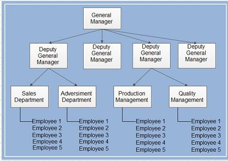
The hierarchical model organizes data elements as tabular rows, one for each instance of entity. Consider a company’s organizational structure. At the top we have a General Manager (GM). Under him we have several Deputy General Managers (DGMs). Each DGM looks after a couple of departments and each department will have a manager and many employees. When represented in hierarchical model, there will be separate rows for representing the GM, each DGM, each department, each manager and each employee. The row position implies a relationship to other rows. A given employee belongs to the department that is closest above it in the list and the department belongs to the manager that is immediately above it in the list and so on as shown.
In the hierarchical data model, records are linked with other superior records on which they are dependent and also on the records, which are dependent on them. A tree structure may establish one-to-many relationship. Figure illustrates the structure of a family. Great grandparent is the root of the structure. Parents can have many children exhibiting one to many relationships. The great grandparent record is known as the root of the tree. The grandparents and children are the nodes or dependents of the root. In general, a root may have any number of dependents. Each of these dependent may have any number of lower level dependents, and so on, with no restriction of levels.
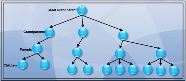
The different elements (e.g. records) present in the hierarchical tree structure have Parent-Child relationship. A Parent element can have many children elements but a Child element cannot have many parent elements. That is, hierarchical model cannot represent many to many relationships among records.
Another example, of hierarchical· model is shown. It shows a database of Customer-Loan, here a customer can take multiple loans and there is also a provision of joint loan where more than one person can take a joint loan. As shown, CI customer takes a single loan Ll of amount 10000 jointly with customer C2. Customer C3 takes two loans L2 of amount 15000 and L3 of amount 25000.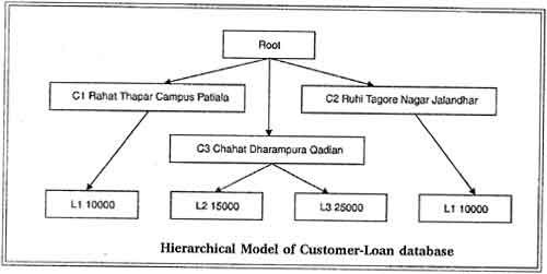 Sample Database
In order to understand the hierarchical data model better, let us take the example of the sample database consisting of supplier, parts and shipments. The record structure and some sample records for supplier, parts and shipments elements are as given in following tables.
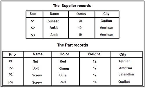
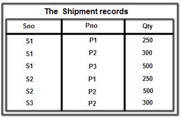
We assume that each row in Supplier table is identified by a unique SNo (Supplier Number) that uniquely identifies the entire row of the table. Likewise each part has a unique Pno (Part Number). Also we assume that no more than one shipment exists for a given supplier/part combination in the shipments table.
Hierarchical View for the Suppliers-Parts Database
The tree structure has parts record superior to supplier record. That is parts form the parent and supplier forms the children. Each of the four trees figure, consists of one part record occurrence, together with a set of subordinate supplier record occurrences. There is one supplier record for each supplier of a particular part. Each supplier occurrence includes the corresponding shipment quantity.
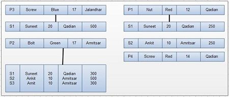
For example, supplier S3 supplies 300 quantities of part P2. Note that the set of supplier occurrences for a given part occurrence may contain any number of members, including zero (for the case of part P4). Part PI is supplied by two suppliers, S1 and S2. Part P2 is supplied by three suppliers, S1, S2 and S3 and part P3 supplied by only supplier SI as shown in figure.
Operations on Hierarchical Model
There are four basic operations Insert, Update, Delete and Retrieve that can be performed on each model. Now, we consider in detail that how these basic operations are performed in hierarchical database model.
Insert Operation: It is not possible to insert the information of the supplier e.g. S4 who does not supply any part. This is because a node cannot exist without a root. Since, a part P5 that is not supplied by any supplier can be inserted without any problem, because a parent can exist without any child. So, we can say that insert anomaly exists only for those children, which has no corresponding parents.
Update Operation: Suppose we wish to change the city of supplier S1 from Qadian to Jalandhar, then we will have to carry out two operations such as searching S1 for each part and then multiple updations for different occurrences of S1. But, if we wish to change the city of part P1 from Qadian to Jalandhar, then these problems will not occur because there is only a single entry for part P I and the problem of inconsistency will not arise. So, we can say that update anomalies only exist for children not for parent because children may have multiple entries in the database.
Delete Operation: In hierarchical model, quantity information is incorporated into supplier record. Hence, the only way to delete a shipment (or supplied quantity) is to delete the corresponding supplier record. But such an action will lead to loss of information of the supplier, which is not desired. For example: Supplier S2 stops supplying 250 quantity of part PI, then the whole record of S2 has to be deleted under part PI which may lead to loss the information of supplier. Another problem will arise if we wish to delete a part information and that part happens to be only part supplied by some supplier. In hierarchical model, deletion of parent causes the deletion of child records also and if the child occurrence is the only occurrence in the whole database, then the information of child records will also lost with the deletion of parent. For example: if we wish to delete the information of part P2 then we also lost the information of S3, S2 and S1 supplier. The information of S2 and S1 can be obtained from P1, but the information about supplier S3 is lost with the deletion of record for P2.
Record Retrieval: Record retrieval methods for hierarchical model are complex and asymmetric which can be clarified with the following queries:
Query1: Find the supplier number for suppliers who supply part P2.
Solution: In order to get this information, first we search the information of parent P2 from database, since parent occurs only once in the whole database, so we obtain only a single record for P2. Then, a loop is constructed to search all suppliers under this part and supplier numbers are printed for all suppliers.
Algorithm
get [next] part where PNO=P2;
do until no more shipments under this part;
get next supplier under this part;
print SNO;
end;
Query2: Find part numbers for parts supplied by supplier S2
Solution: In order to get required part number we have to search S2 under each part. If supplier S2, is found under a part then the corresponding part number is printed, otherwise we go to next part until all the parts are searched for supplier S2.
Algorithm
do until no more parts;
get next part;
get [next] supplier under this part where SNO=S2;
if found then print PNO;
end;
In above algorithms “next” is interpreted relative the current position (normally the row most recently accessed; for the initial case we assume it to be just prior to the first row of the table). We have placed square brackets around “next” in those statements where we expect at the most one occurrence to satisfy the specified conditions.
Since, both the queries involved different logic and are complex, so we can conclude that retrieval operation of this model is complex and asymmetric.
Conclusion: As explained earlier, we can conclude that hierarchical model suffers from the Insertion anomalies, Update anomalies and Deletion anomalies, also the retrieval operation is complex and asymmetric, and thus hierarchical model is not suitable for all the cases.
Record
A collection of field or data items values that provide information on an entity. Each field has a certain data type such as integer, real or string. Records of the same type are group into record type.
Parent Child Relationship Type
It is 1:N relation between two record type. The record type 1 side is parent record type and one on the N side is called child record type of the PCR type.
Advantages
1. Simplicity
Data naturally have hierarchical relationship in most of the practical situations. Therefore, it is easier to view data arranged in manner. This makes this type of database more suitable for the purpose.
2. Security
These database system can enforce varying degree of security feature unlike flat-file system.
3. Database Integrity
Because of its inherent parent-child structure, database integrity is highly promoted in these systems.
4. Efficiency: The hierarchical database model is a very efficient, one when the database contains a large number of I: N relationships (one-to-many relationships) and when the users require large number of transactions, using data whose relationships are fixed.
Disadvantages
1. Complexity of Implementation: The actual implementation of a hierarchical database depends on the physical storage of data. This makes the implementation complicated.
2. Difficulty in Management: The movement of a data segment from one location to another cause all the accessing programs to be modified making database management a complex affair.
3. Complexity of Programming: Programming a hierarchical database is relatively complex because the programmers must know the physical path of the data items.
4. Poor Portability: The database is not easily portable mainly because there is little or no standard existing for these types of database.
5. Database Management Problems: If you make any changes in the database structure of a hierarchical database, then you need to make the necessary changes in all the application programs that access the database. Thus, maintaining the database and the applications can become very difficult.
6. Lack of structural independence: Structural independence exists when the changes to the database structure does not affect the DBMS’s ability to access data. Hierarchical database systems use physical storage paths to navigate to the different data segments. So, the application programs should have a good knowledge of the relevant access paths to access the data. So, if the physical structure is changed the applications will also have to be modified. Thus, in a hierarchical database the benefits of data independence are limited by structural dependence.
7. Programs Complexity: Due to the structural dependence and the navigational structure, the application programs and the end users must know precisely how the data is distributed physically in the database in order to access data. This requires knowledge of complex pointer systems, which is often beyond the grasp of ordinary users (users who have little or no programming knowledge).
8. Operational Anomalies: As discussed earlier, hierarchical model suffers from the Insert anomalies, Update anomalies and Deletion anomalies, also the retrieval operation is complex and asymmetric, thus hierarchical model is not suitable for all the cases.
9. Implementation Limitation: Many of the common relationships do not conform to the l:N format required by the hierarchical model. The many-to-many (N:N) relationships, which are more common in real life are very difficult to implement in a hierarchical model.
Network Model
The popularity of the network data model coincided with the popularity of the hierarchical data model. Some data were more naturally modeled with more than one parent per child. So, the network model permitted the modeling of many-to-many relationships in data.
In 1971, the Conference on Data Systems Languages (CODASYL) formally defined the network model. The basic data modeling construct in the network model is the set construct. A set consists of an owner record type, a set name, and a member record type. A member record type can have that role in more than one set; hence the multi-parent concept is supported.
An owner record type can also be a member or owner in another set. The data model is a simple network, and link and intersection record types (called junction records by IDMS) may exist, as well as sets between them. Thus, the complete network of relationships is represented by several pairwise sets; in each set some (one) record type is owner (at the tail of the network arrow) and one or more record types are members (at the head of the relationship arrow).
Usually, a set defines a 1:M relationship, although 1:1 is permitted. The CODASYL network model is based on mathematical set theory.
Network model is a collection data in which records are physically linked through linked lists .A DBMS is said to be a Network DBMS if the relationships among data in the database are of type many-to-many. The relationship among many-to-many appears in the form of a network.
Thus the structure of a network database is extremely complicated because of these many-to-many relationships in which one record can be used as a key of the entire database. A network database is structured in the form of a graph that is also a data structure.
Relational Model
The Relational Model was the first theoretically founded and well thought out Data Model, proposed by EfCodd in 1970, then a researcher at IBM. It has been the foundation of most database software and theoretical database research ever since.
The Relational Model is a depiction of how each piece of stored information relates to the other stored information. It shows how tables are linked, what type of links are between tables, what keys are used, what information is referenced between tables. It’s an essential part of developing a normalized database structure to prevent repeat and redundant data storage.
The basic idea behind the relational model is that a database consists of a series of unordered tables (or relations) that can be manipulated using non-procedural operations that return tables. This model was in vast contrast to the more traditional database theories of the time that were much more complicated, less flexible and dependent on the physical storage methods of the data.. The RELATIONAL database model is based on the Relational Algebra, set theory and predicate logic.
It is commonly thought that the word relational in the relational model comes from the fact that you relate together tables in a relational database. Although this is a convenient way to think of the term, it’s not accurate. Instead, the word relational has its roots in the terminology that Codd used to define the relational model. The table in Codd’s writings was actually referred to as a relation (a related set of information).
In fact, Codd (and other relational database theorists) use the terms relations, attributes and tuples where most of us use the more common terms tables, columns and rows, respectively (or the more physical—and thus less preferable for discussions of database design theory—files, fields and records).
The relational model can be applied to both databases and database management systems (DBMS) themselves. The relational fidelity of database programs can be compared using Codd’s 12 rules (since Codd’s seminal paper on the relational model, the number of rules has been expanded to 300) for determining how DBMS products conform to the relational model.
When compared with other database management programs, Microsoft Access fares quite well in terms of relational fidelity. Still, it has a long way to go before it meets all twelve rules completely.
Object-Oriented Model
An object-oriented database management system (OODBMS, but sometimes just called “object database” or ODBMS) is a DBMS that stores data in a logical model that is closely aligned with an application program’s object model. Of course, an OODBMS will have a physical data model optimized for the kinds of logical data model it expects.
Object oriented database models have been around since the seventies when the concept of object oriented programming was first explored. It is only in the last ten or fifteen years that companies are utilizing object oriented DBMSs (OODBMS). The major problem for OODBMSs was that relational DBMSs (RDBMS) were already implemented industry wide.
OODBMS should be used when there is a business need, high performance required, and complex data is being used. Due to the object oriented nature of the database model, it is much simpler to approach a problem with these needs in terms of objects.
The result can be a performance increase of ten to one thousand times while writing as little as 40% of the code (this is because it requires no intermediate language such as SQL; everything is programmed in the OO language of choice). This code can be directly applied to a database, and thus saves time and money in development and maintenance.
An object-oriented database interface standard is being developed by an industry group, the Object Data Management Group (ODMG). The Object Management Group (OMG) has already standardized an object-oriented data brokering interface between systems in a network.
 Dinesh Thakur holds an B.C.A, MCDBA, MCSD certifications. Dinesh authors the hugely popular