This was one the earlier CRTs to produce color displays. Coating phosphors of different compounds can produce different colored pictures. But the basic problem of graphics is not to produce a picture of a predetermined color, but to produce color pictures, with the color characteristics chosen at run time.
The basic principle behind colored displays is that combining the 3 basic colors –Red, Blue and Green, can produce every color. By choosing different ratios of these three colors we can produce different colors – millions of them in-fact. We also have basic phosphors, which can produce these basic colors. So, one should have a technology to combine them in different combinations.
There are two popular techniques for producing color displays with a CRT are:
We’ll be covering the following topics in this tutorial:
Beam Penetration method
This CRT is similar to the simple CRT, but it makes use of multi coloured phosphorus of number of layers. Each phosphorus layer is responsible for one colour. All other arrangements are similar to simple CRT. It can produce a maximum of 4 to 5 colours
The organization is something like this – The red, green and blue phosphorus are coated in layers – one behind the other. If a low speed beam strikes the CRT, only the red colored phosphorus is activated, a slightly accelerated beam would activate both red and green (because it can penetrate deeper) and a much more activated one would add the blue component also.
But the basic problem is a reliable technology to accelerate the electronic beam to precise levels to get the exact colors – it is easier said than done. However, a limited range of colors can be conveniently produced using the concept.
The Shadow – Mask method.

This works, again, on the principle of combining the basic colors – Red, green and Blue – in suitable proportions to get a combination of colors, but it’s principle is much more sophisticated and stable.
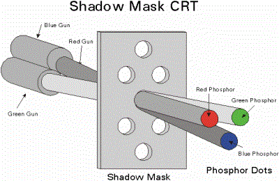
The shadow mask CRT, instead of using one electron gun, uses 3 different guns placed one by the side of the other to form a triangle or a “Delta” as shown. Each pixel point on the screen is also made up of 3 types of phosphors to produce red, blue and green colors. Just before the phosphor screen is a metal screen, called a “shadow mask”.
This plate has holes placed strategically, so that when the beams from the three electron guns are focused on a particular pixel, they get focused on particular color producing pixel only i.e. If for convenience sake we can call the electronic beams as red, blue and green beams (though in practice the colors are produced by the phosphors, and until the beams hit the phosphor dots, they produce no colors), the metal holes focus the red beam onto the red color producing phosphor, blue beam on the blue producing one etc. When focused on to a different pixel, the red beam again focuses on to the red phosphor and so on.
Now, unlike the beam penetration CRTs where the acceleration of the electron beam was being monitored, we now manipulate the intensity of the 3 beams simultaneously. If the red beam is made more intense, we get more of red color in the final combination etc. Since fine-tuning of the beam intensities is comparatively simple, we can get much more combination of colors than the beam penetration case. In fact, one can have a matrix of combinations to produce a wide variety of colors.
The shadow mask CRT, though better than the beam penetration CRT in performance, is not without it’s disadvantages. Since three beams are to be focused, the role of the “Shadow mask” becomes critical. If the focusing is not achieved properly, the results tend to be poor. Also, since instead of one pixel point in a monochrome CRT now each pixel is made up of 3 points (for 3 colors), the resolution of the CRT (no. of pixels) for a given screen size reduces.
Another problem is that since the shadow mask blocks a portion of the beams (while focusing them through the holes) their intensities get reduced, thus reducing the overall brightness of the picture. To overcome this effect, the beams will have to be produced at very high intensities to begin with. Also, since the 3 color points, though close to each other, are still not at the same point, the pictures tend to look like 3 colored pictures placed close by, rather than a single picture. Of course, this effect can be reduced by placing the dots as close to one another as possible.
The above displays are called refresh line drawing displays, because the picture vanishes (typically in about 100 Milli seconds ) and the pictures have to be continuously refreshed so that the human persistence of vision makes them see as static pictures. They are costly on one hand and also tend to flicker when complex pictures are displayed (Because refreshing because complex).
These problems are partly overcome by devices with inherent storage devices – i.e. they continue to display the pictures, till they are changed or at least for several minutes without the need of being refreshed. We see one such device called the Direct View Storage Tube (DVST) below.
 Dinesh Thakur holds an B.C.A, MCDBA, MCSD certifications. Dinesh authors the hugely popular