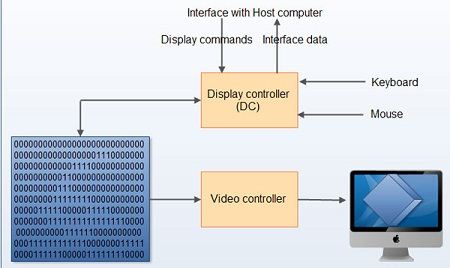
All operations on computers are in terms of 0’s and 1’s and hence figures are also to be stored in terms of 0’s and 1’s. Thus a picture file, when viewed inside the memory, can be no different from other files – a string of Os and 1s. However, their treatment when they are to be displayed makes the difference. Pictures are actually formed with the help of frame-buffer display as follows
Frame buffer display contains a frame buffer, which is a storage device and stores the image in terms of 0’s and 1’s. It contains the 0’s and 1’s in terms of 8’s, or multiples of 8’s in a row. These 0’s and 1’s will be read by display controller one line at a time and sent to the screen after converting them from digital to analog. The display controller reads the contents of frame buffer one line at a time or entire digits at time. These digital images after converting into the analog will be displayed on the screen. The following figure illustrates this 
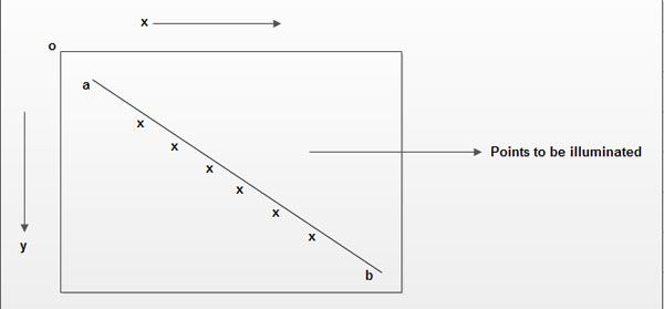
Figures can be stored and drawn in two ways – either by line drawing or by Raster graphic methods. In the line drawing scheme, the figures are represented by equations – for example a straight line can be represented by the equation y=mx+c, a circle by x2+y2=r2 etc. If (x, y) are representative points, then all these (x,y) value pairs which satisfy the equations form a part of the figure while those that do not, lie outside the figure. Thus, to generate any figure, obviously the equation of the figure is to be known. Then all points that satisfy the equation are evaluated. These are the points to be illuminated on the screen. 
A moving electronic beam, as we know illuminates the screen, or the monitor. Whenever the beam is switched on, the electrons illuminate the phosphorescent screen and display a point. In the line drawing schemes, this beam is made to traverse the path of the figure to be traced and we get the figure we need. For example, in the above cited example if the electron beam is made to move from a to be along the points, we get the line.
The raster scan mechanism uses a different technique and is often found more convenient to manipulate and operate with. In this case, a “frame buffer”, (a chunk of memory) is made to store the pixel values. (Remember, the screen can be thought of as having beam made up of a number of horizontal rows of pixels (picture cells), each pixel representing a point on the picture. In fact the number of such horizontal and vertical points indicate higher resolutions and therefore better pictures.
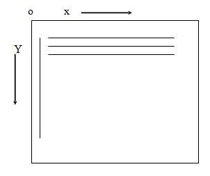
Typical resolutions are like 640 X 480, 860 X 640, 1024 x 860 etc., where the figures indicate the number of rows and the number of pixels along each row respectively on a computer screen (unlike in standard mathematics) the top left hand point indicates the origin or the point (0,0) and the distances are measured horizontally and vertically as shown).

Now, assuming a 1024 x 1024 point screen, any figure that is to be displayed within this space. The “frame buffer” stores “status” of each of these pixels – say 0 indicates the pixel is off and hence is not a part of the picture and 1 indicates it is a part of the picture, and is to be displayed. This data is used to display the pictures.
 Dinesh Thakur holds an B.C.A, MCDBA, MCSD certifications. Dinesh authors the hugely popular