VLANs have the primary role to enable easier configuration and management of large corporate networks built around many bridges. There are several implementation strategies for these virtual networks.
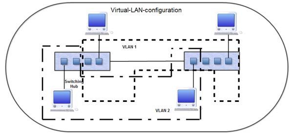
Virtual LAN is software that is employed to provide multiple networks in single hub by grouping terminals connected to switching hubs. It is a LANs that is grouped together by logical addresses into a virtual LAN instead of a physical LAN through a switch. The switch can support many virtual LANs that operate with having different network addresses or as subnets. Users within a virtual LAN are grouped either by IP address or by port address, with each node attached to the switch via a dedicated circuit. Users also can be assigned to more than one virtual LAN.
The VLAN can be defined as a broadcast domain in which the broadcast address reaches all stations belonging to the VLAN. Communications within the VLAN can be secured, and between those two controlled separate VLANs. 
A router is generally required to establish communication between VLANs.
Several types of VLAN are defined according to the groupings of system stations:
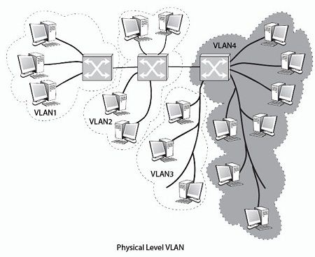
• The level of physical or VLAN level 1, which includes stations belonging to the same physical network or multiple physical networks but connected by a common address management. Figure shows a level of VLAN 1.

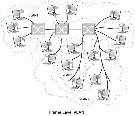
• The level of VLAN frame, or more precisely the MAC VLAN level, or the level of VLAN 2, where it is the MAC addresses that includes the stations belonging to the same VLAN. As the stations may be located in geographically distant locations, the challenge is to achieve automatic broadcast on all stations of the VLAN, a station can belong to several VLANs simultaneously. Figure shows a level of VLAN frame.

• The packet level VLAN or VLAN level 3 are combinations of stations according to their level address 3. These level 3 addresses can be an IP address or IP address sub address, called mask IP subnet. It is necessary, in this case, to match the packet-level address and the frame level. ARP type protocol (Address Resolution Protocol) performs this address match.
If an institution wants large structure its network, it can create virtual networks according to criteria that are specific to it. Generally, a geographical criterion was used to perform simple communication between the different sites of the institution. The address of the VLAN is added to the structure of the Ethernet frame or the frame of another technology, since the VLAN structuring is not only about Ethernet environments.
The IEEE 802.1q VLAN Tagging standard
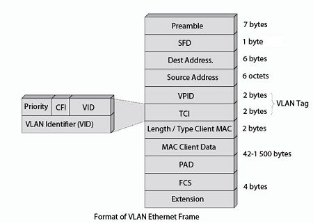
The format of the Ethernet VLAN frame, described in the standards IEEE 802.1Q and IEEE 802.3ac, is illustrated in FIG.
The VLAN identifier (VLAN Tag) 4 bytes contains a first field VPID (VLAN protocol identifier) and a field TCI (Tag Control Information). The VLAN tag is inserted between the source address and the Length field / Mac client type. The length of the Ethernet frame of 1518 bytes passes 1522 bytes with this field. The VPID field is set to 0x81-00 when the TCI field is present.

The TCI field itself contains three fields:
• A 3-bit priority field for up to eight priority levels.
• A field a bit, the bit CFI (Canonical Format Indicator), which is not used in the IEEE 802.3 networks, must be set to 0 in this case. He is credited with the value 1 for encapsulating Token Ring frames.
• A field VID (VLAN Identifier) of 12 bits, indicating the address of the VLAN.
The role of the 3-bit priority field is important because it allows you to assign priorities to the various multimedia applications. This functionality is described in IEEE 802.1p standard. Eight priority levels used to allow real-time services like speech.
Characteristics of VLAN
- Individual VLAN acts as a separate LAN, thus sharing the traffic among VLANs and reducing the congestion
- Workstations can be provided with full bandwidth at each port
- Relocation of terminals becomes easy
It requires a good deal of effort to develop the switch database and identify the various logical addresses.
 Dinesh Thakur holds an B.C.A, MCDBA, MCSD certifications. Dinesh authors the hugely popular