Virtual Circuit (VC) – In this type connection, DTE selects the links to be used before communication to connect a receiver just as in the case of telephone network. In other words, we may say that a pre-planned route established before any packets are sent. A communications arrangement in which data from a source user may be passed to a destination user over various real circuit configurations during a single period of communication and the Information about the routing of packets is stored in all nodes throughout the set-up phase. Virtual circuits generally set up on a per connection basis and are disconnected when the connection is terminated and after that, the information in the network is erased. However, a permanent virtual circuit can be established as an option to provide a dedicated link between two facilities.
We’ll be covering the following topics in this tutorial:
Permanent Virtual Circuit (PVC)
PVC is a virtual circuit used to establish a long-term connection between DTE at the sending and receiving end. The user can use the channel in the same manner as used in case of leased line. That is the user is fixed and always connected to logical channel. The main features of PVC are having a long-term association which is Identical to the data transfer phase of a virtual call. It also eliminates the need for repeated connection set-up and clearing. Basically switching nodes store the Information permanently for the transfer of packets between’ two stations or more and thus creating a permanent virtual circuit (PVC).
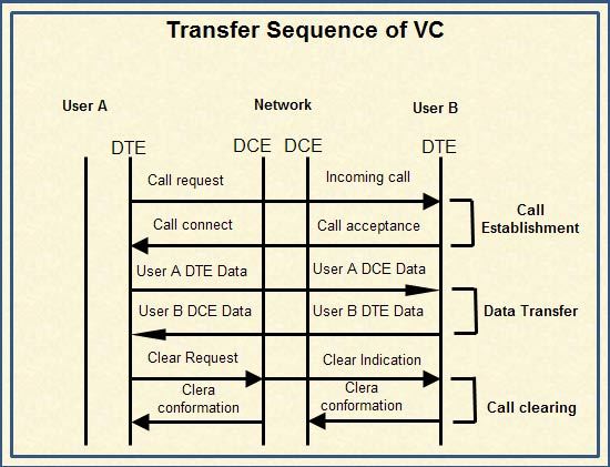
Transfer Sequence of VC
Data transfer procedure For VC is shown in Figure. Before the actual communication, a call request and call accept packets establish connection that is called handshake. By doing this connection/call (logical channel) gets established. The same is cleared after completion of communication. Each packet contains a virtual circuit Identifier instead of destination address.
• To establish a connection on a VC, the calling DTE sends a Call Request packet, which includes the address of the remote DTE to be contacted.
• The destination DTE decides whether or not to accept the call (the Call request packet includes the sender’s DTE address, as well as other Information that the called DTE can use to decide whether or not to accept the call). A call is accepted by issuing a Call Accepted packet, or cleared by issuing a Clear Request packet. .
• Once the originating DTE receive the Call Accepted packet, the virtual circuit is established and data transfer may take place. When either DTE wishes to terminate the call, a Clear Request packet is sent to the remote DTE, which responds with a Clear Confirmation packet.
• The destination for each packet is identified by means of the Logical Channel Identifier (LCI) or Logical Channel Number (LCN). This allows the X.25 network to route each packet to its intended DTE.

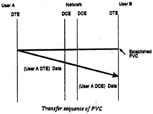
Transfer Sequence of PVC
The data communication procedure for PVC shown in the figure. By established PVC in advance data packet can be transmitted directly.

 Dinesh Thakur holds an B.C.A, MCDBA, MCSD certifications. Dinesh authors the hugely popular