• Skip to main content
  • Skip to primary sidebar
  • Skip to secondary sidebar
  • Skip to footer

Computer Notes

Library
    • Computer Fundamental
    • Computer Memory
    • DBMS Tutorial
    • Operating System
    • Computer Networking
    • C Programming
    • C++ Programming
    • Java Programming
    • C# Programming
    • SQL Tutorial
    • Management Tutorial
    • Computer Graphics
    • Compiler Design
    • Style Sheet
    • JavaScript Tutorial
    • Html Tutorial
    • Wordpress Tutorial
    • Python Tutorial
    • PHP Tutorial
    • JSP Tutorial
    • AngularJS Tutorial
    • Data Structures
    • E Commerce Tutorial
    • Visual Basic
    • Structs2 Tutorial
    • Digital Electronics
    • Internet Terms
    • Servlet Tutorial
    • Software Engineering
    • Interviews Questions
    • Basic Terms
    • Troubleshooting
Menu

Header Right

Home » Graphics » Graphics Device

What is VGA (video graphics array)?

By Dinesh Thakur

VGA, which stands for video graphics array, is currently the most popular standard for PC screen display equipment. Technically, a VGA is a type of video adapter (circuitry in the computer that controls the screen). IBM developed the VGA for its PS/2 line of computers (the name “Video Graphics Array” is an IBM trademark), but loads of other manufacturers make VGA add-in boards (that plug into a slot in the pc) and VGA chips (in some pcs, these VGA chips are built right into the main part of the computer, the motherboard). A VGA monitor is a monitor that works with a VGA adapter.

A standard VGA system displays up to 640x 480 pixels (little dots) on the screen, with up to 16 different colors at a time. In lower resolution, 320x 200 pixels, the screen can show up to 256 colors at once. These specifications are much better than the older video adapter standards, the CGA and EGA, but they’re not good enough for many people. If you’re buying a new system or replacing an older video adapter, make sure you get a “Super VGA” adapter, which can handle higher resolutions (800x 600 or higher) and many more colors. Remember though, that the higher the resolution and the more colors you have to work with, the slower the display will function, and the more memory you’ll need on the card.

Unlike EGA and CGA monitors, VGA monitors are analog devices, meaning they can display an infinite range of colors (the number of colors you see is limited by the VGA adapter, not the monitor).

When you’re shopping for a VGA monitor, keep several points in mind. First, if you want to use higher resolutions than the VGA standard of 640x 480, you need a multiscan monitor-a plain VGA monitor will not work at higher resolutions. Second, some VGA monitors give a sharper image than others. Partly, this depends on the dot Pitch: a monitor with a smaller dot-pitch (like .28mm) will have better image clarity than one with a larger dot-pitch (like .39mm).

A VGA monitor requires an interface card and a cable. You need to know how much memory is on the card. You may want to add more memory, especially if you plan to create and use complex graphic or photographic images. The VGA is the current standard right now in monitors, and as such is usually the most readily available.

Explain vector vs. raster graphics.

By Dinesh Thakur

Vector graphics are stored in the computer as a set of mathematical formulas describing the shapes that make up each image. When you display a vector graphic on the screen or print it, these formulas are converted into the patterns of dots you can see. Because the dots are not specified unit! you display or print the graphic, you can change the size of the image without any loss of quality, and the image will always appear at the highest resolution of whatever screen or printer you’re using. The term vector graphics means exactly the same thing as object-oriented (or just object) graphics.

The contrasting term is raster graphic (the terms raster and bitmapped are synonymous). In a raster graphic, the actual dots that make up the image you see are defined when the graphic is created, so the resolution is fixed; changing the size will make the image look coarse or muddy. See paint program for an example illustrating the fixed resolution.

Most Macintosh people use the terms object-oriented and bitmapped rather than vector and raster. Most PC people use both pairs of terms interchangeably.

What is Multiscan?

By Dinesh Thakur

Multiscan refers to a type of computer monitor that automatically matches the synchronizing signals sent from the computer’s video adapter (the video circuitry). On a standard television-type monitor, the image you see is formed by a single beam of electrons scanning lickety-split across the picture tube. The beam starts at one corner, traces a narrow horizontal line, then moves down a bit and traces the next line. The speed with which the beam travels horizontally and vertically (the horizontal and vertical “scan frequencies”), must match the synchronizing signals from the computer’s video circuits.


The problem is, the synch signals vary with each type of video adapter for PCs(EGAS, VGAS, Super VGA, and so on). Since the scan rate is fixed in an ordinary monitor, you can only use the monitor with one type of video adapter-a VGA monitor only works with a VGA adapter, and so on. By contrast, a multiscan monitor will work with many different types of adapters, within limits.

When you buy, be sure your monitor’s range of scan frequencies matches all the adapters you may use it with. At a minimum, it should have a 50-75 Hz (hertz, times per second) vertical frequency and a 30-50 kHz (kilohertz) horizontal frequency. The vertical frequency measures how fast the entire screen is “repainted,” and is also called the refresh rate. You should also insist on a variable frequency monitor, one that can match any frequency within those ranges, rather than one that simply operates at several different but fixed frequencies. And, by the way, multiscan monitors are more expensive than fixed-scan rate monitors.

There’s much less inconsistency in the Macintosh world, so a multiscan monitor isn’t so important. But many of them will work with a Mac

What is Monitor?

By Dinesh Thakur

Monitor is another word for the computer screen. But “monitor” encompasses the whole piece of equipment, rather than just the screen part that you look at. You also might hear a monitor called a display, as in “Oooh, I got a new two-page display,” or VDT(video display terminal), as in newspaper journalism, or CRT (cathode ray tube), which is the technical term for a picture tube. However, flat panel screens like LCDS are not referred to as monitors, even if they’re housed externally from a computer.


Some monitors are built right into the computers, like in the small Macintoshes. When you purchase a larger Macintosh or most other kinds of computers, you must buy the monitor separate from the computer itself (that’s why they’re called “modular”). Monitor size is measured like a television, from one corner to the diagonally opposite corner.

Some monitors are monochrome, meaning they can show only one color on a background, like black on white (Macs), green on black, or amber on black (pcs). Grayscale monitors can display different shades of gray, rather than imitating the different shades with combinations of black and white dots. And there are many different color monitors. A color monitor can display any of several levels of resolution and can display varying numbers of colors, determined by several factors, such as amount of memory in the computer or the type of card that is controlling the monitor. See the section in Appendix A on how to read a computer monitor advertisement.

What is Low Resolution?

By Dinesh Thakur

If an image is displayed on your screen or printed on the page in low-res (short for low resolution), that means you are seeing a low-grade quality. Some graphics are just low-resolution to begin with, such as graphics made in the paint file format at 72 dots per inch. Some graphics are created as complex, high-resolution images, but you may choose to display them on the screen or print them in low-res just to save time, since it takes longer for a screen or a printer to create the high- resolution version.


For instance, if you are producing a brochure on your computer and in the brochure you have several high-resolution photographs in full color, it can take a long time to turn pages or change views. So you can choose to view these images in low resolution while you are working, just so you can move around the screen faster. You can choose to print them in low resolution just so you get an idea of the look of the brochure without waiting to reproduce the entire high resolution images.

The lower the resolution, the less information there is in a given amount of space (in a square inch, for instance). It may mean that each pixel in that square inch of the screen is not providing enough information to resolve the image clearly, or it may mean there are less printed dots per inch on the page.

What is LED (light emitting diode)?

By Dinesh Thakur

LED stands for light emitting diode. You know those little lights on your computer, usually near the hard disk, that flash while the computer is working? Those are LEDs. They work on the principle of electroluminescence, which refers to substances that glow when you apply electricity. LEDs were used in digital watches, but now all digital watches use LCDs because LCD stakes less power.

LEDs are ordinary diodes (the most basic electronic component) that, due to their composition, happen to glow red, green, or amber when energized by a couple of volts. They use less power than incandescent bulbs and last over 100,000 hours.

What is Interlaced or Non-Interlaced Monitors?

By Dinesh Thakur

In a standard television-like computer monitor, an image is produced on the screen by a beam of electrons sweeping rapidly across the surface of the picture tube, lighting up the screen as it passes. Starting at the top, the beam traces one horizontal row across the screen, shifts down a bit and does another row, and so on, until the full height of the screen has been covered.


In an interlaced monitor, the electron beam takes two passes to form a complete image: it skips every other row on the first pass, and then goes back and fills in the missing rows. A non-interlaced monitor does the whole job in one pass, tracing each row consecutively. Interlaced monitors are easier to build and therefore cheaper, but as you can guess-they aren’t as good as non-interlaced monitors. The problem is that all things being equal, it takes twice as long to create the complete screen image on an interlaced monitor. That’s long enough to spoil the illusion that you’re looking at a steady picture, and the image on the screen flickers annoyingly. 

What is Dot Pitch?

By Dinesh Thakur

The dot pitch of a color monitor measures the size of the tiny individual dots of phosphorescent material that coat the back side of the picture tube’s face. The dot pitch helps determine how sharp the image looks, independent of the resolution (which is measured in pixels). A smaller dot pitch is better.


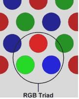
Here’s the technical scoop: Each point of light on a color monitor is formed from a triad of three separate dots of phosphor: one that glows red, one green, and one blue (the color you finally see depends on how intensely each dot in the triad is excited by the picture tube’s electronic beam). The dot pitch is the vertical distance between the centre of one dot and the next like-colored dot directly above or below it (the way the dots are arranged, pairs of like-colored dots are always two rows apart). The farther apart the centres of the dots are, the bigger the dots and the fuzzier the image. All other things being equal, a monitor with a smaller dot pitch is preferable to one with a larger dot pitch, though other factors are more important in determining image sharpness below a certain dot pitch threshold.

A dot pitch of .28 mm or smaller is ideal for 14- or 15-inch monitors; a dot pitch of .31mm or less for 17- to 20-inch monitors. Resolution, in pixels, is determined by the video circuitry in your computer. Depending on the resolution and on the dot pitch, a single pixel may occupy 4 to 16 separate phosphor triads.

What is CGA (Color Graphics Adapter)?

By Dinesh Thakur

CGA stands for color graphics adapter, the first IBM video card to permit graphics on the screen. We’re lucky they’ve come out with better models, because CGA graphics are gawdawful crude. With a CGA, your screen can show up to 640 dots across by 200 dots up and down, with only one color. Even at that maximum resolution, pictures look really blocky and out of proportion. Pictures will look even more blocky if you want 4 colors on the screen at once, since you’re then limited to 320 dots across and 200 down. If you can tolerate a totally chunky display of 160 by 200 dots, you can get a maximum of 16 colors on a CGA. Wow!

A CGA can display text too, but the characters are fuzzy looking and squished together, so they’re hard to read. And you may see an annoying sparkling effect called snow when you scroll the text. So don’t buy a computer with a CGA. And if someone gives you one, put in a VGA instead.

Many other companies besides IBM have produced video cards that work just like a CGA. Some pcs, including most laptops made prior to 1990, come with built-in CGA-Compatible circuitry. These variations are generically referred to as CGAs or CGA systems, trademarks notwithstanding. And since people don’t look at the video circuits too often, they generally end up using the term CGA to refer to their monitor, as in “I have a CGA screen.”

What is LCD (Liquid Crystal Display)?

By Dinesh Thakur

LCD stands for liquid crystal display. Your digital watch uses an LCD to show you the time, and most portable computers use an LCD to display the screen. There is actually a liquid compound, liquid crystals, sandwiched between two grids of electrodes. The electrodes can selectively turn on the different cells or pixels in the grid to create the image you see.

An LCD consists of a layer of gooey material-the liquid crystals themselves-between two polarizing filters. These filters are sheets of plastic that let through only those light waves traveling parallel to a particular plane. Between the filters and the liquid crystal layer runs a thin grid of transparent electrodes.

The two polarizing filters are arranged so that their polarizing planes are at right angles. That setup would block light from passing through except for the fact that the liquid crystal molecules are “twisted.” They pivot the light coming through the first filter, aligning the light with the polarizing plane of the second filter. Since the light makes it all the way through both filters, the screen looks light in color. However, the liquid crystal molecules that are controlled by a particular electrode become untwisted when a current is applied. Light no longer passes through the second filter, and you see a black or colored dot on the screen. Most LCDs are passive matrix designs, in which each dot, or pixel, on the screen shares electrodes with other dots. Active matrix designs, which produce much brighter, more colorful images, have a separate transistor for each pixel, which allows greater control over the current for that pixel.

In “supertwist” LCDS, the liquid crystal molecules have a more pronounced twist than in the ordinary screens, improving contrast. The chemist’s term “nematic” refers to the molecular structure of the crystals-all LCDs use nematic crystals, so this term is used in ads just to impress you.

Although you can read an LCD screen in room light, the contrast is mediocre at best. Today, the LCD screens on most computers are illuminated by backlighting or edge lighting (fluorescent-type lights mounted behind the screen or along either side).


Cathode Ray Tube (CRT/Monitor)

By Dinesh Thakur

One of the basic and commonly used display devices is Cathode Ray Tube (CRT). A cathode ray tube is based on the simple concept that an electronic beam, when hits a phosphorescent surface, produces a beam of light (momentarily – though we later describe surfaces that produce light intensities lashing over a period of time).

 Further, the beam of light itself can be focused to any point on the screen by using suitable electronic / magnetic fields. The direction and intensity of the fields will allow one to determine the extent of the defection of the beam. Further these electronic / magnetic fields can be easily manipulated by using suitable electric fields with this background. In following section we describe the structure and working of the simple CRT.


Simple CRT makes use of a conical glass tube. At the narrow end of the glass tube an electronic gun is kept. This gun generates electrons that will be made to pass through the magnetic system called yoke. This magnetic system is used for making the electronic beam to fall throughout the broad surface of the glass tube. The broad surface of the glass tube contains a single coat of high quality phosphorus. This reflects the electronic beam makes it to fall on the computer screen.


          cathod Ray Tube

A pair of focusing grids – one horizontal and another vertical does the actual focusing of the electronic beam on to the screen. Electronic or magnetic fields operate these grids. Depending on the direction (positive or negative) and the intensity of the fields applied to them, the beam is deflected horizontally (or vertically) and thus, by using a suitable combination of these focusing grids; the beam can be focused to any point on the screen.


So, we now have a mechanism wherein any point on the screen can be illuminated (or made dark by simply switching off the beam). Hence, from a graphics point of view, any picture can be traced on the screen by the electron beam by suitably and continuously manipulating the focusing grids and we get to see the picture on the screen “A basic graphic picture” of course, since the picture produced vanishes once the beam is removed, to give the effect to continuity, we have to keep the beam retracing the picture continuously – (Refreshing).

How are refresh rates calculated? And What is the Importance of Refresh Rates

By Dinesh Thakur

Factors in determining refresh rates

A refresh rate is dependent upon a monitor’s horizontal scanning frequency and the number of horizontal lines displayed.The horizontal scanning frequency is the number of times the electron beam sweeps one line and returns to the beginning of the next in one second. Horizontal scanning frequency is measured in kilohertz (kHz).

 A monitor with a horizontal scanning frequency of 110 kHz means 110,000 lines are scanned per second. The number of horizontal lines on the screen depends upon the monitor’s resolution. If a monitor is set to a resolution of 1024 x 768 then there are 768 horizontal lines (1024 is the number of pixels on one line).

For a monitor set to a 1280 x 1024 resolution, there are 1024 horizontal lines. Additionally, the time it takes for the electron beam to return to the top of the screen and begin scanning again must be taken into account. This is roughly 5% of the time it takes to scan the entire screen. Therefore, the total is multiplied by 0.95 to calculate the maximum refresh rate.

Calculate maximum refresh rates

The following formula is used to calculate maximum refresh rates

fV = fH / # of horizontal lines x 0.95

fV = vertical scanning frequency (refresh rate)

fH = horizontal scanning frequency

Example: A monitor with a horizontal scanning frequency of 96 kHz at a resolution of 1280 x 1024 would have the following refresh rate based on the calculation above.

fV = 96,000 / 1024 x 0.95

fV = 89.06

This figure is rounded down to produce a maximum refresh rate of 89Hz.

If the same monitor is set to a resolution of 1600 x 1200, then the equation will be as follows:

fV = 96,000 / 1200 x 0.95

fV = 76

The maximum refresh rate at this resolution is 76 Hz.

Importance of Refresh Rates 

When choosing a monitor, one of the factors that the customer usually considers is the refresh rate. A high refresh rate is important in providing a clear picture and avoiding eye fatigue.

An image appears on screen when electron beams strike the surface of the screen in a zig-zag pattern. A refresh rate is the number of times a screen is redrawn in one second and is measured in Hertz (Hz). Therefore, a monitor with a refresh rate of 85 Hz is redrawn 85 times per second.

A monitor should be “flicker-free meaning that the image is redrawn quickly enough so that the user cannot detect flicker, a source of eye strain. Today, a refresh rate of 75 Hz or above is considered to be flicker-free

Difference Between Raster Scan Display and Random Scan Display

By Dinesh Thakur

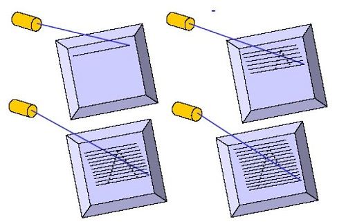
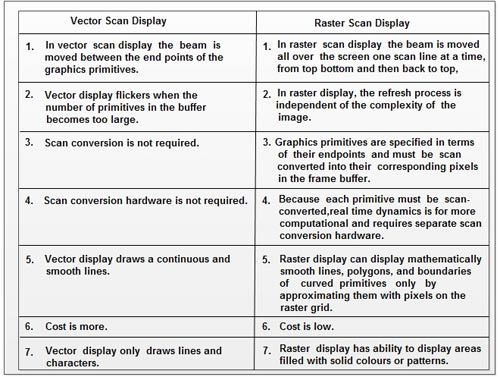
Raster Scan methods have increasingly become the dominant technology since about 1975. These methods use the TV type raster scan. The growth in the use of such methods has been dependent on rapidly decreasing memory prices and on the availability of cheap scan generating hardware from the TV industry.

 The screen is coated with discrete dots of phosphor, usually called pixels, laid out in a rectangular array. The image is then determined by how each pixel is intensified.  The representation of the image used in servicing the refresh system is thus an area of memory holding a value for each pixel. This memory area holding the image representation is called the frame buffer.

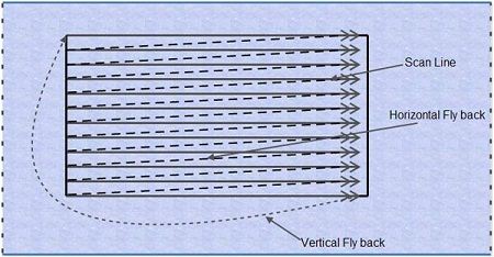
The values in the frame buffer are held as a sequence of horizontal lines of pixel values from the top of the screen down. The scan generator then moves the beam in a series of horizontal lines with fly-back (non-intensified) between each line and between the end of the frame and the beginning of the next frame. This is illustrated below.

Ranom Scan

Unlike random-scan which is a line drawing device, refresh CRT is a point-plotting device. Raster displays store the display primitives (lines, characters, shaded and patterned areas) in a refresh buffer. Refresh buffer (also called frame buffer) stores the drawing primitives in terms of points and pixels components This scan is synchronized with the access of the intensity values held in the frame buffer.

Raster Scan

The maximum number of points that can be displayed without overlap by a system is called the resolution and is quoted as the number of points per horizontal line versus the number of horizontal lines. Typical resolutions are 640*480, 1024*768, and 1280*1024. The maximum resolution is determined by the characteristics of the monitor and/or by the memory capacity available for storing the frame buffer.

Random Scan Display 

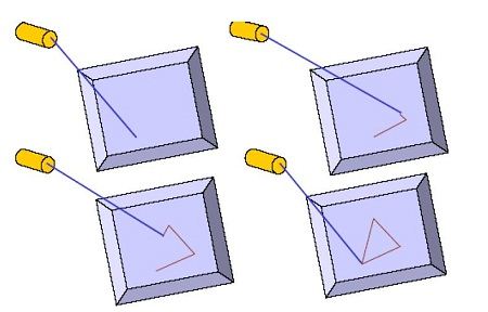
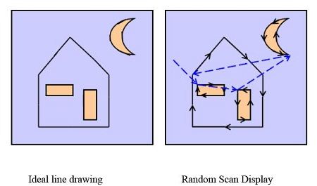
Random scan displays, often termed vector Vector, Stroke, and Line drawing displays, came first and are still used in some applications. Here the characters are also made of sequences of strokes (or short lines). The electron gun of a CRT illuminates straight lines in any order. The display processor repeatedly reads a variable ‘display file’ defining a sequence of X,Y coordinate pairs and brightness or color values, and converts these to voltages controlling the electron gun.

Random

In random scan display an electron beam is deflected from endpoint to end-point.


The order of deflection is dictated by the arbitrary order of the display commands. The display must be refreshed at regular intervals – minimum of 30 Hz (fps) for flicker-free display

Ideal Line Drawing

More Difference Between Vector Scan Display and Raster Scan Display

                       Vector Scan vs Raster Scan Display

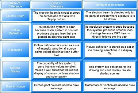
Difference between Raster Scan System and Random Scan System

By Dinesh Thakur

Raster random


Magnet-Optical Storage Media

By Dinesh Thakur

There are used for erasable disks. MO system includes basic principles of both magnetic & optical storage systems. MO systems write magnetically & read optically. It has two standard forms : 5.25 inches & 3.5 inches.

Plasma displays, Thin film electro-luminescent display, Light-emitting diode ( LED ), Liquid Crystal Display (LCD)

By Dinesh Thakur

Plasma displays are bright, have a wide color gamut, and can be produced in fairly large sizes, up to 262 cm (103 inches) diagonally. They have a very low-luminance “dark-room” black level, creating a black some find more desirable for watching movies. The display panel is only about 6 cm (2½ inches) thick, while the total thickness, including electronics, is less than 10 cm (4 inches).

 Plasma displays use as much power per square meter as a CRT or an AMLCD television. Power consumption will vary greatly depending on what is watched on it. Bright scenes (say a football game) will draw significantly more power than darker scenes. The xenon and neon gas in a plasma television is contained in hundreds of thousands of tiny cells positioned between two plates of glass.

Long electrodes are also sandwiched between the glass plates, in front of and behind the cells. The address electrodes sit behind the cells, along the rear glass plate. The transparent display electrodes, which are surrounded by an insulating dielectric material and covered by a magnesium oxide protective layer, are mounted in front of the cell, along the front glass plate. Control circuitry charges the electrodes that cross paths at a cell, creating a voltage difference between front and back and causing the gas to ionize and form a plasma; as the gas ions rush to the electrodes and collide, photons are emitted.  

In a monochrome plasma panel, the ionizing state can be maintained by applying a lowlevel voltage between all the horizontal and vertical electrodes – even after the ionizing voltage is removed. To erase a cell all voltage is removed from a pair of electrodes. This type of panel has inherent memory and does not use phosphors. A small amount of nitrogen is added to the neon to increase hysteresis. In color panels, the back of each cell is coated with a phosphor.

The ultraviolet photons emitted by the plasma excite these phosphors to give off colored light. The operation of each cell is thus comparable to that of a fluorescent lamp. Every pixel is made up of three separate sub pixel cells, each with different colored phosphors. One sub pixel has a red light phosphor, one sub pixel has a green light phosphor and one sub pixel has a blue light phosphor. These colors blend together to create the overall color of the pixel, analogous to the “triad” of a shadowmask CRT.

Thin film electro-luminescent display

Electroluminescence is the result of radiative recombination of electrons and holes in a material (usually a semiconductor). The excited electrons release their energy as photons – light. Prior to recombination, electrons and holes are separated either as a result of doping of the material to form a p-n junction (in semiconductor electroluminescent devices such as LEDs), or through excitation by impact of high-energy electrons accelerated by a strong electric field (as with the phosphors in electroluminescent displays).

Powder phosphor-based electroluminescent panels are frequently used as backlights to liquid crystal displays. They readily provide a gentle, even illumination to the entire display while consuming relatively little electric power. They do, however, require relatively high voltage. Recently, blue, red and green emitting thin film electroluminescent materials have been developed that offer the potential for long life and full color electroluminescent displays. In either case, the EL material must be enclosed between two electrodes and at least one electrode must be transparent to allow the escape of the produced light.

Glass coated with indium oxide or tin oxide is commonly used as the front (transparent) electrode while the back electrode is or is coated with reflective metal. Additionally, other transparent conducting materials, such as carbon nanotubes coatings or PEDOT can be used as the front electrode. Unlike neon and fluorescent lamps, EL lamps are not negative resistance devices so no extra circuitry is needed to regulate the amount of current flowing through them. In principle, EL lamps can be made in any color. EL devices have low power consumption when compared with neon signs, and have a wide range of applications such as their use on advertising boards and safety signs.

Light-emitting diode ( LED )  

A light-emitting diode (LED) is a semiconductor diode that emits incoherent narrow-spectrum light when electrically biased in the forward direction of the p-n junction. This effect is a form of electroluminescence. An LED is usually a small area source, often with extra optics added to the chip that shapes its radiation pattern. The color of the emitted light depends on the composition and condition of the semi conducting material used, and can be infrared, visible, or near-ultraviolet. An LED can be used as a regular household light source.

Like a normal diode, an LED consists of a chip of semi conducting material impregnated, or doped, with impurities to create a p-njunction. As in other diodes, current flows easily from the p-side, or anode, to the n-side, or cathode, but not in the reverse direction. Charge-carriers—electrons and holes—flow into the junction from electrodes with different voltages. When an electron meets a hole, it falls into a lower energy level, and releases energy in the form of a photon. The wavelength of the light emitted, and therefore its color, depends on the band gap energy of the materials forming the p-n junction.

In silicon or germanium diodes, the electrons and holes recombine by a non-radiative transition which produces no optical emission, because these are indirect band gap materials. The materials used for an LED have a direct band gap with energies corresponding to near-infrared, visible or near-ultraviolet light. LEDs are usually built on an n-type substrate, with an electrode attached to the ptype layer deposited on its surface.

P-type substrates, while less common, occur as well. Many commercial LEDs, especially GaN/InGaN, also use sapphire substrate. Substrates that are transparent to the emitted wavelength, and backed by a reflective layer, increase the LED efficiency. The refractive index of the package material should match the index of the semiconductor, otherwise the produced light gets partially reflected back into the semiconductor, where it may be absorbed and turned into additional heat, thus lowering the efficiency. An anti-reflection coating may be added as well.

Liquid Crystal Display (LCD)  

An active matrix liquid crystal display (AMLCD) is a type of flat panel display, currently the overwhelming choice of notebook computer manufacturers, due to light weight, very good image quality, wide color gamut, and response time. The most common example of an active matrix display contains, besides the polarizing sheets and cells of liquid crystal, a matrix of thin-film transistors (TFTs) to make a TFT LCD.

Each pixel of an LCD typically consists of a layer of molecules aligned between two transparent electrodes, and two polarizing filters, the axes of transmission of which are (in most of the cases) perpendicular to each other. With no liquid crystal between the polarizing filters, light passing through the first filter would be blocked by the second (crossed) polarizer. The surface of the electrodes that are in contact with the liquid crystal material are treated so as to align the liquid crystal molecules in a particular direction. This treatment typically consists of a thin polymer layer that is unidirectionally rubbed using, for example, a cloth.

The direction of the liquid crystal alignment is then defined by the direction of rubbing. When a voltage is applied across the electrodes, a torque acts to align the liquid crystal molecules parallel to the electric field, distorting the helical. This reduces the rotation of the polarization of the incident light, and the device appears gray. If the applied voltage is large enough, the liquid crystal molecules in the center of the layer are almost completely untwisted and the polarization of the incident light is not rotated as it passes through the liquid crystal layer. This light will then be mainly polarized perpendicular to the second filter, and thus be blocked and the pixel will appear black.

By controlling the voltage applied across the liquid crystal layer in each pixel, light can be allowed to pass through in varying amounts thus constituting different levels of gray.Both the liquid crystal material and the alignment layer material contain ionic compounds. If an electric field of one particular polarity is applied for a long period of time, this ionic material is attracted to the surfaces and degrades the device performance.

This is avoided either by applying an alternating current or by reversing the polarity of the electric field as the device is addressed. When a large number of pixels is required in a display, it is not feasible to drive each directly since then each pixel would require independent electrodes. Instead, the display is multiplexed. In a multiplexed display, electrodes on one side of the display are grouped and wired together (typically in columns), and each group gets its own voltage source. On the other side, the electrodes are also grouped (typically in rows), with each group getting a voltage sink.

Shadow Mask CRT (Cathode Ray Tube)

By Dinesh Thakur

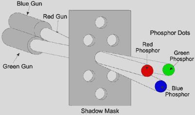
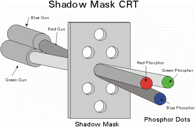
In Shadow Mask CRT tiny holes in a metal plate separate the colored phosphors in the layer behind the front glass of the screen. The holes are placed in a manner ensuring that electrons from each of the tube’s three cathode guns reach only the appropriately-colored phosphors on the display. All three beams pass through the same holes in the mask, but the angle of approach is different for each gun.

 The spacing of the holes, the spacing of the phosphors, and the placement of the guns is arranged so that for example the blue gun only has an unobstructed path to blue phosphors. The red, green, and blue phosphors for each pixel are generally arranged in a triangular shape (sometimes called a “triad”). All early color televisions and the majority of computer monitors, past and present, use shadow mask technology.


Traditionally, shadow masks have been made of materials which temperature variations cause to expand and contract to the point of affecting performance. The energy the shadow mask absorbs from the electron gun in normal operation causes it to heat up and expand, which leads to blurred or discolored (see doming) images. The invar shadow mask is composed of the nickel-iron alloy invar.


Therefore it expands and contracts much less than other materials in response to temperature changes. This property allows displays made with this technology to provide a clearer, more accurate picture. It also reduces the amount of long-term stress and damage to the shadow mask that can result from repeated expand/contract cycles, thus increasing the display’s life expectancy.


In other words, In Shadow Mask CRT, before the stream of electrons produced by the CRT’s cathode reach the phosphor coated faceplate, it encounters the shadow mask, a sheet of metal etched with a pattern of holes. The mask is positioned in the glass funnel of the CRT during manufacture and the phosphor is coated onto the screen so that electrons coming from the red, green and blue gun positions only land on the appropriate phosphor.

                                                                              RGB Triad

Stray electrons strike the shadow mask and are absorbed by it, generating a great deal of heat, which in turn causes the metal to expand. To allow flatter CRTs to be made, the metal most commonly used now for shadow masks is Invar, an alloy of iron and nickel. The metal has a low coefficient of expansion and its name derives from the supposed invariability of its dimensions when heat is applied. In reality, its dimensions are not completely invariable and the build up of heat in a shadow mask can lead to a form of distortion known as doming, where the centre of the mask bulges towards the faceplate slightly.


                                                     Shadow Mask

An alternative to the shadow mask which is less prone to distortion, the aperture grille , was included as part of the design of Trinitron CRTs by Sony in 1968 and Mitsubishi in its Diamondtron products in the early 1990s.


What is Color CRT Display? Explain Beam-penetration and Shadow-mask method

By Dinesh Thakur

This was one the earlier CRTs to produce color displays. Coating phosphors of different compounds can produce different colored pictures. But the basic problem of graphics is not to produce a picture of a predetermined color, but to produce color pictures, with the color characteristics chosen at run time.

The basic principle behind colored displays is that combining the 3 basic colors –Red, Blue and Green, can produce every color. By choosing different ratios of these three colors we can produce different colors – millions of them in-fact. We also have basic phosphors, which can produce these basic colors. So, one should have a technology to combine them in different combinations.

 There are two popular techniques for producing color displays with a CRT are:

Beam Penetration method 

This CRT is similar to the simple CRT, but it makes use of multi coloured phosphorus of number of layers. Each phosphorus layer is responsible for one colour. All other arrangements are similar to simple CRT. It can produce a maximum of 4 to 5 colours 

The organization is something like this – The red, green and blue phosphorus are coated in layers – one behind the other. If a low speed beam strikes the CRT, only the red colored phosphorus is activated, a slightly accelerated beam would activate both red and green (because it can penetrate deeper) and a much more activated one would add the blue component also.

But the basic problem is a reliable technology to accelerate the electronic beam to precise levels to get the exact colors – it is easier said than done. However, a limited range of colors can be conveniently produced using the concept.

The Shadow – Mask method.

         shadowmask-beams

  This works, again, on the principle of combining the basic colors – Red, green and Blue – in suitable proportions to get a combination of colors, but it’s principle is much more sophisticated and stable.

The shadow mask CRT, instead of using one electron gun, uses 3 different guns placed one by the side of the other to form a triangle or a “Delta” as shown. Each pixel point on the screen is also made up of 3 types of phosphors to produce red, blue and green colors. Just before the phosphor screen is a metal screen, called a “shadow mask”. 

This plate has holes placed strategically, so that when the beams from the three electron guns are focused on a particular pixel, they get focused on particular color producing pixel only i.e. If for convenience sake we can call the electronic beams as red, blue and green beams (though in practice the colors are produced by the phosphors, and until the beams hit the phosphor dots, they produce no colors), the metal holes focus the red beam onto the red color producing phosphor, blue beam on the blue producing one etc. When focused on to a different pixel, the red beam again focuses on to the red phosphor and so on.

Now, unlike the beam penetration CRTs where the acceleration of the electron beam was being monitored, we now manipulate the intensity of the 3 beams simultaneously. If the red beam is made more intense, we get more of red color in the final combination etc. Since fine-tuning of the beam intensities is comparatively simple, we can get much more combination of colors than the beam penetration case. In fact, one can have a matrix of combinations to produce a wide variety of colors.

The shadow mask CRT, though better than the beam penetration CRT in performance, is not without it’s disadvantages. Since three beams are to be focused, the role of the “Shadow mask” becomes critical. If the focusing is not achieved properly, the results tend to be poor. Also, since instead of one pixel point in a monochrome CRT now each pixel is made up of 3 points (for 3 colors), the resolution of the CRT (no. of pixels) for a given screen size reduces. 

Another problem is that since the shadow mask blocks a portion of the beams (while focusing them through the holes) their intensities get reduced, thus reducing the overall brightness of the picture. To overcome this effect, the beams will have to be produced at very high intensities to begin with. Also, since the 3 color points, though close to each other, are still not at the same point, the pictures tend to look like 3 colored pictures placed close by, rather than a single picture. Of course, this effect can be reduced by placing the dots as close to one another as possible.

The above displays are called refresh line drawing displays, because the picture vanishes (typically in about 100 Milli seconds ) and the pictures have to be continuously refreshed so that the human persistence of vision makes them see as static pictures. They are costly on one hand and also tend to flicker when complex pictures are displayed (Because refreshing because complex).

These problems are partly overcome by devices with inherent storage devices – i.e. they continue to display the pictures, till they are changed or at least for several minutes without the need of being refreshed. We see one such device called the Direct View Storage Tube (DVST) below.


DVST – Direct View Storage Tube

By Dinesh Thakur

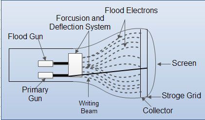
Conceptually the Direct View Storage Tube (DVST) behaves like a CRT with highly persistent phosphor. Pictures drawn on there will be seen for several minutes (40-50 minutes) before fading. It is similar to CRT as far as the electronic gun and phosphor-coated mechanisms are concerned. But instead of the electron beam directly writing the pictures on the phosphor coated CRT screen, the writing is done with the help of a fine-mesh wire grid.

The grid made of very thin, high quality wire, is located with a dielectric and is mounted just before the screen on the path of the electron beam from the gun. A pattern of positive charges is deposited on the grid and this pattern is transferred to the phosphor coated CRT by a continuous flood of electrons. This flood of electrons is produced by a “flood gun” (This is separate frame the electron gun that produces the main electron beam).

Just behind the storage mesh is a second grid called the collector. The function of the collector is to smooth out the flow of flood electrons. Since a large number of electrons are produced at high velocity by the flood gun, the collector grid, which is also negatively charged reduces, the acceleration on these electrons and the resulting low velocity flood pass through the collector and get attracted by the positively charged portions of the storage mesh (Since the electrons are negatively charged), but are repelled by the other portions of the mesh which are negatively charged (Note that the pattern of positive charges residing on the storage mesh actually defines the picture to be displayed).

  DVST

Thus, the electrons attracted by the positive charges pass through the mesh, travel on to the phosphor coated screen and display the picture. Since the collector has slowed the electrons down, they may not be able to produce sharp and bright images. To over come this problem, the screen itself is maintained at a high positive potential by means of a voltage applied to a thin aluminum coating between the tube face and the phosphor.

The dotted circle on the mesh is created by positive charges the flood of electrons hit the mesh at all points. But only those electrons that hit the dotted circle pass through and hit the CRT screen. The negatively charged mesh repels others.

 Since the phosphor is of a very high persistence quality, the picture created on the CRT screen will be visible for several minutes without the need for being refreshed.

 Now the problem arises as to how do we remove the picture, when the time for it’s erasure or modification comes up. The simple method is to apply a positive charge to the negatively charged mesh so that it gets neutralized. This removes all charges and clears the screen. But this technique also produces a momentary flash, which may be unpleasant to the viewer.

This is mainly so when only portions of the picture are to be modified in an interactive manner. Also, since the electrons hit the CRT screen at very low speeds (though they are slightly accelerated in the last part of their journey to the CRT by a positively charged aluminum coating), the contrasts are not sharp. Also, even though the pictures stay for almost an hour, there will be a  gradual degradation because of the accumulation of the background glow.

The  other popular display device is the plasma panel device, which is partly similar to the DVST in principle, but over comes some of the undesirable features of the DVST.


Primary Sidebar

Computer Graphics Tutorials

Computer Graphics

  • CG - Home
  • CG - Introduction
  • CG - Applications
  • CG - Applications
  • CG - Raster Vs Random Scan Display
  • CG - Frame Buffer
  • CG - DVST
  • CG - CRT Display
  • CG - DDA
  • CG - Transformation
  • CG - Cathode Ray Tube
  • CG - Bresenham’s Line Algorithm
  • CG - Pixel
  • CG - Data Compression
  • CG - Clipping
  • CG - Shadow Mask CRT
  • CG - Line Drawing Algorithm
  • CG - Text Clipping
  • CG - Refresh Rates
  • CG - CRT/Monitor
  • CG - Interactive Graphics Display
  • CG - Raster Vs Random Scan System
  • CG - Liquid Crystal Display
  • CG - Scan Converting a Line
  • CG - Monitors Types
  • CG - Display Types
  • CG - Sutherland-Hodgeman Clipping
  • CG - Bitmap
  • CG - Antialiasing
  • CG - Refresh Rates
  • CG - Shadow Mask Vs Beam Penetration
  • CG - Scan Converting a Point
  • CG - Image Resolution
  • CG - Double Buffering
  • CG - Raster Vs Random Scan
  • CG - Aspect Ratio
  • CG - Ambient Light
  • CG - Image Processing
  • CG - Interactive Graphics Displayed
  • CG - Shadow Mask CRT
  • CG - Dithering
  • CG - GUI
  • CG - CLUT
  • CG - Graphics
  • CG - Resolutions Types
  • CG - Transformations Types
  • CG - Half-toning Effect
  • CG - VGA
  • CG - Aliasing
  • CG - CGA

Other Links

  • Computer Graphics - PDF Version

Footer

Basic Course

  • Computer Fundamental
  • Computer Networking
  • Operating System
  • Database System
  • Computer Graphics
  • Management System
  • Software Engineering
  • Digital Electronics
  • Electronic Commerce
  • Compiler Design
  • Troubleshooting

Programming

  • Java Programming
  • Structured Query (SQL)
  • C Programming
  • C++ Programming
  • Visual Basic
  • Data Structures
  • Struts 2
  • Java Servlet
  • C# Programming
  • Basic Terms
  • Interviews

World Wide Web

  • Internet
  • Java Script
  • HTML Language
  • Cascading Style Sheet
  • Java Server Pages
  • Wordpress
  • PHP
  • Python Tutorial
  • AngularJS
  • Troubleshooting

 About Us |  Contact Us |  FAQ

Dinesh Thakur is a Technology Columinist and founder of Computer Notes.

Copyright © 2025. All Rights Reserved.

APPLY FOR ONLINE JOB IN BIGGEST CRYPTO COMPANIES
APPLY NOW