Raster Scan methods have increasingly become the dominant technology since about 1975. These methods use the TV type raster scan. The growth in the use of such methods has been dependent on rapidly decreasing memory prices and on the availability of cheap scan generating hardware from the TV industry.
The screen is coated with discrete dots of phosphor, usually called pixels, laid out in a rectangular array. The image is then determined by how each pixel is intensified. The representation of the image used in servicing the refresh system is thus an area of memory holding a value for each pixel. This memory area holding the image representation is called the frame buffer.
The values in the frame buffer are held as a sequence of horizontal lines of pixel values from the top of the screen down. The scan generator then moves the beam in a series of horizontal lines with fly-back (non-intensified) between each line and between the end of the frame and the beginning of the next frame. This is illustrated below.
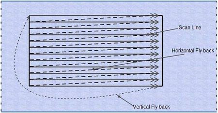
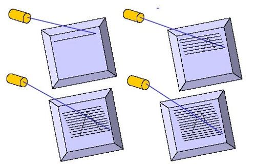
Unlike random-scan which is a line drawing device, refresh CRT is a point-plotting device. Raster displays store the display primitives (lines, characters, shaded and patterned areas) in a refresh buffer. Refresh buffer (also called frame buffer) stores the drawing primitives in terms of points and pixels components This scan is synchronized with the access of the intensity values held in the frame buffer.
The maximum number of points that can be displayed without overlap by a system is called the resolution and is quoted as the number of points per horizontal line versus the number of horizontal lines. Typical resolutions are 640*480, 1024*768, and 1280*1024. The maximum resolution is determined by the characteristics of the monitor and/or by the memory capacity available for storing the frame buffer.
We’ll be covering the following topics in this tutorial:
Random Scan Display
Random scan displays, often termed vector Vector, Stroke, and Line drawing displays, came first and are still used in some applications. Here the characters are also made of sequences of strokes (or short lines). The electron gun of a CRT illuminates straight lines in any order. The display processor repeatedly reads a variable ‘display file’ defining a sequence of X,Y coordinate pairs and brightness or color values, and converts these to voltages controlling the electron gun.
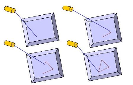
In random scan display an electron beam is deflected from endpoint to end-point.
The order of deflection is dictated by the arbitrary order of the display commands. The display must be refreshed at regular intervals – minimum of 30 Hz (fps) for flicker-free display
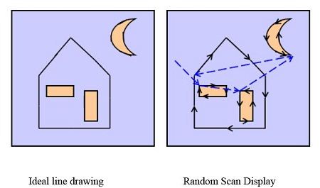
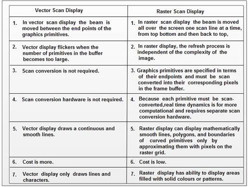
More Difference Between Vector Scan Display and Raster Scan Display
 Dinesh Thakur holds an B.C.A, MCDBA, MCSD certifications. Dinesh authors the hugely popular