Transmission is the method by which computer networks send electrical signals. Data communication is concerned with the process of exchanging data electronically between two communication devices. In a local area network, all communication functions performed through direct cables. Computers located far away are connected through a particular form of the data communication link. The existing telephone or telegraphic network may also use for connecting computers located at remote locations.
The information transmits in the form of electromagnetic signals through a transmission medium. Whether you are collecting numerical statistics from other computers, whether you are sending animated graphics from a design station or ringing a remote control center, information is being transmitted over network connections. The information can be a voice, image, numeric data, characters or codes, any message that is legible and has meaning for the target user, whether it is human or a machine.
There are 2 broad types of signals, analog and digital, which study in detail below.
We’ll be covering the following topics in this tutorial:
Analog Signal Transmission
An analog signal is a continuous waveform that changes smoothly over time. As the wave moves from A to B, it passes through and includes an infinite number of values in, its path. Then an analog data, for example, is the human voice. When someone speaks a wave created that continues in the air. This wave can capture by a microphone and converted into an analog signal.
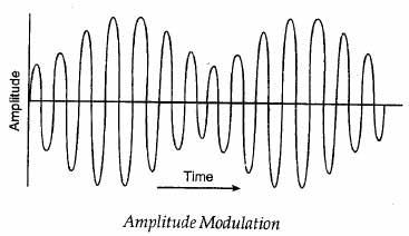
Information is first converted into an electrical signal known as baseband electrical signal. The transmission does by sending this baseband signal directly. A unique process called modulation is used in the analog transmission to accommodate more than one information signal into a single channel. Modulation means varying any one of the parameters of a high-frequency waveform proportional to the amplitude of the baseband signal. The parameters of the carrier often used for the modulation are amplitude, frequency, and phase. A model amplitude modulated waveform is shown in Figure.
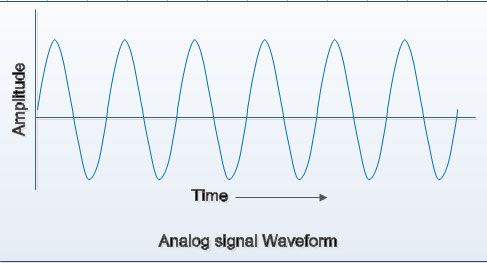
Generally, the signals illustrated by printing them on a pair of perpendicular axes. The vertical axis represents the value or power of the signal. The horizontal axis represents the passage of time. The figure illustrates an analog signal. The curve representing an analog signal is smooth and continuous, passing through an infinite number of points.
Simple analog signals
The sine wave is the basic form of a periodic analog signal. Visualized as the only oscillating curve, its change throughout a cycle is smooth and consistent, a continuous flow, which shown in the below figure. A single arc forms each cycle on the time axis followed by a single arch below him. Sine waves can fully describe three characteristics: Amplitude, period, and frequency and phase.

Amplitude
The amplitude in a graph is the value of the signal at any point on the wave. It is equal to the vertical distance from any point on the wave to the horizontal axis. The maximum amplitude of a sine wave is equal to the highest value it can reach on the vertical axis. In the figure, it clearly shows this characteristic.

The amplitude is measured in volts, amps, or watts, depending on the type of signal. The volts indicate the voltage; the amps indicate the electric current and the watts indicate the power.
The amplitude indicates the height of the signal. The unit of amplitude depends on the type of signal. For electrical signals, the unit is generally in volts, amps or watts.
Period and frequency
The period refers to the amount of time, in seconds, that you need a signal to complete a cycle. The frequency indicates the number of periods in a second. The sequence of a signal is the number of cycles per seconds. The concept of period and frequency illustrated in the figure.
Units of the period: The period expressed in seconds. The communications industry uses five units to measure the period: second, milliseconds, microseconds, nanoseconds, and picoseconds. See the reference of the units in the table.
Frequency units: The frequency expressed in hertz (HZ), in honor of the German physicist Heinrich Rudolf Hertz. The communication industry uses five units to measure frequency: Herzio, kilohertz, megahertz, gigahertz and terahertz. See the table.
Mathematically, the relationship between frequency and period is that each of them is the multiplicative inverse of the other. If one occurs, the other can be immediately derived.
Frequency = 1 / period period = 1 / frequency.
It can conclude that the period is the amount of time it takes a signal to complete a cycle; the frequency is the number of cycles per second. It can also say that frequency is the speed of change concerning time. Changes in a short period indicate high frequency. Changes in an ample space of time indicate low frequency.
Phase
The term phase describes the position of the wave relative to the instant of time 0. If one thinks of the wave as something that can be moved forward or backward along the time axis, the phrase describes the magnitude of that displacement. It Indicates the status of the first cycle.
The phrase describes the position of the waveform relative to the instant of time 0.
The phase measured in degrees or radians (360 degrees is 2π radians). A phase shift of 360 degrees corresponds to a displacement of an entire period; a phase shift of 180 degrees corresponds to a displacement of half the period; A phase shift of 90 degrees corresponds to a quarter displacement. See figure.
A visual comparison of the amplitude, frequency, and phase provide a useful reference for understanding its functions. You can introduce changes in the three attributes of the signal and control them electronically. This control provides the basis for all telecommunications.
Digital Signal Transmission
Digital data transmission is the transmission of discrete data using two distinct electric states. A ‘1’ for “on” and ‘0’ for “off” represents these two states. The transition between the values of a digital signal is instantaneous, like a light that turns on and off. Digital communication is more efficient than analog communication due to its discrete nature. Communication between computers is carried out in digital, as computers can recognize only binary data.
The vertical lines of the digital signal show that there is a sudden jump between one value and another of the signal. The flat and high regions indicate that these values fixed. A significant difference between the analog and digital signal is that the analog signal changes continuously concerning time, while the digital signal changes instantaneously.
Digital signals also can be modulated or encoded to represent binary data. Following are some of the techniques used in current state strategies
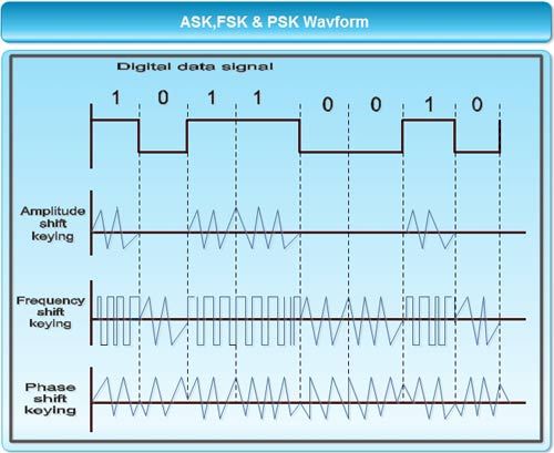
• Amplitude shift keying encodes data using two signals of same frequency but different amplitudes. For example, a binary a might be represented by a 1volt signal and a binary 1might be represented by a 4 volts signal.
• Frequency shift keying encodes binary data by varying the signal’s frequency between two or more values. For example, the signal used for representing a binary 0 would be in one frequency and the signal for a binary 1 would be in some other frequency.
• Phase shift keying encodes binary data by varying the phase of the signal to indicate a value. For example, a 180″ phase-shifted signal could represent binary 1, and signal without phase shift could represents a binary 0. Figure illustrates the three keying schemes.
Decomposition of a digital signal
A digital signal can decompose into an infinite number of pure sine waves called harmonics, each of which has a different amplitude, frequency, and phase. It means that when a transmission medium sends a digital signal, an infinite number of simple signals sent. To receive a replica of the digital signal, all frequency components must be transferred correctly through the transmission medium. If any of the components are not sent well through the medium, the receiver gets a corrupt signal. Since there is no practical means (such as a cable) that is capable of transferring the full range of frequencies, there is always some corruption.
As it could be observed, a digital signal shows greater precision since it has two finite intervals one (1) and zero (0).
Advantages of digital signals
1. Faced with attenuation, it can be amplified and rebuilt at the same time, thanks to signal regeneration systems.
2. It has error detection and correction systems, at the reception.
3. Ease for signal processing. Any operation is easily achievable through any editing or signal processing software.
4. Allows infinite generation without loss of quality. This advantage is only applicable to optical disk formats; The digital magnetic tape, although to a lesser extent than the analog one (which only supports a maximum of 4 or 5 generations), also loses information with multigeneration.
5. Digital signals are less affected by ambient noise compared to analog signals.
Disadvantages of digital signals
1. You need a previous analog-digital conversion and subsequent decoding at the time of receipt.
2. It requires precise synchronization between the clock times of the transmitter concerning those of the receiver.
3. The digital signal requires more bandwidth than the analog signal to be transmitted.
 Dinesh Thakur holds an B.C.A, MCDBA, MCSD certifications. Dinesh authors the hugely popular