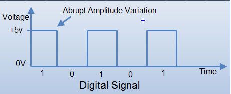
In digital circuit, a signal is represented in discrete states or logic levels. Digital signals are non-continuous and change in individual steps. They consist of pulses with discrete levels. The value of each pulse is constant but there is an abrupt change from one digit to next.
The signals in all present-day electronic digital systems have only two discrete values and are said to be binary. The digital-system design is restricted to use binary signals because of lower reliability of many valued electronic circuits. A circuit with ten states, using one discrete voltage value for each state, can be designed, but it would possess a very low reliability of operation. On the other hand, a circuit that has only two (ON or OFF) signal values can be constructed easily and is very reliable. Due to all these considerations, digital systems are constrained to take discrete values which are further constrained to take binary values.
Most digital circuits use two voltage levels labeled “Low” (0) and “High” (1). Often “Low” will be near 0 volts and “High” will be a higher depending on the supply voltage in use. The Below Fig. Shows a digital signal.

DIGITALTERMINOLOGY
Before going in further details of digital systems we shall first understand the basic terms and logics that are essential for the working of the digital electronics system.
(a) Logic Voltage Levels: Digital signals are represented by the two voltage levels which are referred to as logic voltage levels. A level logic is a logic in which the voltage levels represent logic 1 or logic O. There are two types of logics.
1. Positive Logic
2. Negative Logic
A positive logic system is the one in which higher of the two voltage levels rpresents the logic 1 and lower of the two voltage levels represents the logic O. A negative logic system is the one in which the lower of the two voltage levels represents the logic 1 and. the higher of the two voltage levels represent the logic O. So if two voltage levels are OV and +5V, then in the positive logic system, the OV represents a logic ‘0’ and the +5V represents a logic ‘1’. In negative logic system, it is the reverse, OV represents a logic’ l’ and +5V represents a logic ‘0’, (see in fig)

Unless or otherwise specified, all the signals are dealt with positive logic. Each logic gate is represented by a particular graphic symbol.
(b) Waveform: This refers to the shape and form of a signal such as a wave moving in a solid, liquid or gaseous medium. An instrument called oscilloscope can be used to pictorially represent the wave as a repeating image on a CRT or LCD screen. Some common periodic waveforms include sine waves, square wave etc. A digital waveform is generally in form of square wave.
(C) Digital Circuit: An electronic circuit that accepts and processes binary data according to the rules of Boolean logic (AND, OR NOT etc.) The simplest forms of digital circuits are built from logic gates, the building blocks of digital computer.
(d) Bit: Bit (‘Binary digit’) is a smallest unit of information storage and communication. It is the maximum amount of information that can be stored by a device or any other physical system that can normally exist in only two distinct states. These states are often interpreted as binary digits o and 1. They may also be interpreted as logical values, either true or false or two settings of a switch, either ‘on’ or ‘off’.
In modem computing devices, a bit is usually represented by an electrical voltage or current pulse, or by the electrical state of a flip-flop circuit. For devices using positive logic, a digit value of 1 is represented by a positive voltage relative to the electrical ground voltage (upto 5 volts in TTL designs), while a digit value of 0 is represented by 0 volts. In semiconductor memory, the two values of a bit may be represented by two levels of electrical charge stored in a capacitor.
(e) Nibble: It is equivalent to combination of four binary digits. For example: 1101, 1001, 1110 are all nibbles.
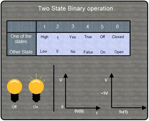
(I)Binary state terminology: The following table summarizes the binary state terminology.

 Dinesh Thakur holds an B.C.A, MCDBA, MCSD certifications. Dinesh authors the hugely popular