• Skip to main content
  • Skip to primary sidebar
  • Skip to secondary sidebar
  • Skip to footer

Computer Notes

Library
    • Computer Fundamental
    • Computer Memory
    • DBMS Tutorial
    • Operating System
    • Computer Networking
    • C Programming
    • C++ Programming
    • Java Programming
    • C# Programming
    • SQL Tutorial
    • Management Tutorial
    • Computer Graphics
    • Compiler Design
    • Style Sheet
    • JavaScript Tutorial
    • Html Tutorial
    • Wordpress Tutorial
    • Python Tutorial
    • PHP Tutorial
    • JSP Tutorial
    • AngularJS Tutorial
    • Data Structures
    • E Commerce Tutorial
    • Visual Basic
    • Structs2 Tutorial
    • Digital Electronics
    • Internet Terms
    • Servlet Tutorial
    • Software Engineering
    • Interviews Questions
    • Basic Terms
    • Troubleshooting
Menu

Header Right

Home » Graphics » Two Dimensional Transformations

What is Halftone?

By Dinesh Thakur

The process by which CONTINUOUS TONE photographs are reproduced in print (for example in newspapers and magazines) by reducing them to a grid of tiny dots. (The resulting image is also commonly known as a halftone.) Each individual dot is printed using a single coloured ink of fixed intensity, and the intensity of colour the reader perceives is controlled by varying the size and density of the dots to reveal more or less of the underlying white paper.

The superficial similarity between this use of dots in printing and the PIXELS that constitute computer images is misleading, since pixels actually vary in colour and intensity rather than size. When computer-generated pictures are prepared for printing, each pixel gets broken up into a sub-grid of halftone dots that simulate its tonal value spatially. The pixel and halftone grids may interfere with each other and cause the problem called SCREEN CLASH.
What is Gouraud Shading?

By Dinesh Thakur

An algorithm employed in 3D GRAPHICS to fool the eye into seeing as a smoothly curving surface an object that is actually constructed from a mesh of polygons. Gouraud’s algorithm requires the colour at each vertex of a polygon to be supplied as data, from which it INTERPOLATES the colour of every PIXEL inside the polygon: this is a relatively fast procedure, and may be made faster still if implemented in a hardware GRAPHICS ACCELERATOR chip. 

What is Ray Trace?

By Dinesh Thakur

Ray tracing is an incredibly complex method of producing shadows, reflections, and refractions in high-quality, three-dimensionally simulated computer graphics. Ray tracing calculates the brightness, the reflectivity, and the transparency level of every object in the image. And it does this backwards. That is, it traces the rays of light back from the viewer’s eye to the object from which the light was bounced off from the original light source, taking into consideration along the way any other objects the light was bounced off or refracted through .

What is Rasterize or Rasterizing?

By Dinesh Thakur

To understand what rasterizing does, first you need to know a little about the images in the computer: Bitmapped (raster) graphics and fonts are created with tiny little dots. Object-oriented (vector) graphics and fonts are created with outlines. Output devices, like printers (except for some plotters) and monitors can only print or display images using dots, not outlines. This means that when an object-oriented graphic or font is output to a printer that prints in dots per inch (as most of them do) or to a monitor that displays in pixels (as most of them do), the outlines must be turned into dots. This process of turning the outlines of the objects into dots is called rasterizing. Everything you see on your monitor has been rasterized. Everything you print has been rasterized.

When you print object-oriented and PostScript images and fonts to an image setter, the information about building those straight lines goes through a RIP (raster image processor), a piece of hardware that stands between the computer and the image setter (printer). The software in the RIP turns the straight lines into the dots that the image setter will print, in resolutions like 1270 or 2540 dots per inch

When you output (print) to a laser printer that understands PostScript, the computer chip inside the PostScript printer rasterizes the images so they can be printed in dots, usually with a resolution of 300 to 600 dots per inch

When the image is displayed (output) on the monitor, it has actually been rasterized so that it could be created out of the pixels on the screen.

And if you have a non-Postscript printer, you should read the definition for Adobe Type Manager to better understand how that software rasterizes your fonts, both to the monitor and to the printer.

What is Greyscale?

By Dinesh Thakur

Some computer screens are grayscale, rather than plainblack-and white (monochrome). On a black-and-white screen, there is only one bit of information being sent to each pixel (dot), so the pixels on the screen are either on (white) or off (black). On a greyscale monitor, anywhere from 2 to 16 bits of information are sent to each pixel, so it is possible to display gray tones in the pixels, rather than just black or white.


The gray tones are the result of some of the bits being on and some being off. If the monitor uses 4 bits, there are 16 possible combinations of on and off, so there are 16 possible shades of gray.

A grayscale is also one variety of TIFF (tagged image file format). When you scan an image as a grayscale, each dot on the screen can register a different gray value. A grayscale tries to approximate the continuous gray tone of photographs.

What is Emulsion?

By Dinesh Thakur

On a piece of photographic film, such as the kind you use to shoot photographs, one side of the film is coated with a layer of chemicals called the emulsion. This is the side that absorbs the light, and the emulsion is scratch able and dull. The non-emulsion side of film looks shinier and is more difficult to scratch. You can see the emulsion side on any negative you have hanging around.


The kind of film that comes out of image setters or that a pressperson uses to print your brochure also has an emulsion side. If you are creating something on your computer that will be output onto film (rather than onto plain paper from your personal printer or onto resin-coated paper from the image setter), you need to know whether the film should be output emulsion side up or down. The only person who can tell you the correct answer is the pressperson who will be printing the final job. She will say, “I need your film right reading emulsion side up” (RREU) or maybe “right reading emulsion side down” (RRED). This means that if you were to lay the film on a light table as if you were reading it properly (reading it right) the emulsion would be up, or facing you, or it would be down, on the side of the film away from you.

What is Texture mapping?

By Dinesh Thakur

Early computer-generated images used shaded objects that had unnaturally smooth surfaces. To produce a textured surface using the techniques discussed would require creating an excessive number of surface pieces that follow all of the complexities of the texture. An alternative to the explosion of surfaces would be to use the techniques of texture mapping. Texture mapping is a technique used to paint scanned images of a texture onto the object being modeled. Through an associated technique, called bump mapping, the appearance of the texture can be improved still further.

What is Flat shading?

By Dinesh Thakur

A problem with the Painter’s and Z-Buffer Algorithms is that they ignore the effects of the light source and use only the ambient light factor. Flat shading goes a bit further and includes the diffuse reflections as well. For each of the planar pieces, an intensity value is calculated from the surface normal, the direction to the light, and the ambient light and diffuse coefficient constants. Since none of these changes at any point on the piece, all of the pixels in that piece will have the same intensity value. The resulting image will appear to be faceted, with ridges running along the boundaries of the pieces that make up an object.

What is alpha channel?

By Dinesh Thakur

An extra layer of information stored in a digital picture to describe transparency or opacity. For each pixel, the alpha channel stores an extra value called alpha, in addition to its red, blue and green values, which indicates the degree of transparency of that pixel.

The display software then mixes the colour of this pixel with the background colour in proportion to its alpha value (so an alpha value of 0.5 would display half foreground and half background), a process called alpha blending.

An alpha channel enables special effects such as blurring or tinting of the background as a transparent object passes across it, and fog or mist effects to suggest distance. Alpha blending is supported as a hardware function by advanced graphics accelerators (AGP).

What is transformation? Type of transformation

By Dinesh Thakur

What is transformation? In  many  cases  a  complex  picture  can  always  be  treated as  a  combination  of  straight line, circles, ellipse etc., and if we are able to generate these basic figures, we can also generate combinations of them.  Once we  have drawn these pictures, the  need arises  to transform these pictures. 

We are  not essentially modifying the pictures, but a picture  in the center of the screen needs to be shifted to the top left hand corner, say, or a picture  needs to be increased to twice it’s size or a picture is to be turned through 900 .  In all these  cases, it  is  possible  to view  the  new  picture  as  really a  new  one  and use  algorithms  to  draw  them, but a better  method is, given their present  form, try to get  their  new counter  parts by operating on the existing data.  This concept is called transformation. 

The three basic transformations are

(i)                 Translation 

(ii)               rotation  and

(iii)             Scaling.

Translation  refers  to the  shifting of  a  point  to some  other  place, whose  distance  with regard to the  present  point  is known. Rotation as  the  name  suggests  is  to rotate  a  point  about an axis.   The axis can be any of the coordinates or simply any other specified line  also. Scaling is the concept of increasing (or decreasing) the size of a picture. (in one or  in either directions.  When  it  is done  in both directions, the  increase or decrease  in both directions  need not be same)   To change the size of the picture, we  increase or decrease  the distance between the end points of the picture and also change the intermediate points  are per requirements.

Translation: 

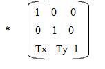
Consider a point P(x1 , y1 ) to be translated to another point Q(x2 , y2 ).  If we know  the point  value (x2, y2) we can directly shift to Q by displaying the pixel (x2, y2).  On the  other  hand, suppose we only know that we  want to shift by a distance of Tx along  x axis  and Ty along  Y axis.   Then obviously the coordinates can be derived by  x2 =x1 +Tx and  Y2 = y1 + Ty .

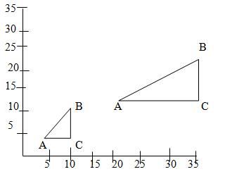
Suppose  we  want  to shift  a  triangle  with  coordinates  at  A(20,10), B(30,100) and C(40,70).   The  shifting to be  done  by  20 units  along  x  axis  and 10 units  along  y  axis. Then the new triangle will be at A1 (20+20, 10+10) B1  (30+20, 10+10) C1 (40+20, 70+10)  In the matrix form [x2 y2 1] = [x1 y1 1]    

                                                              Matrix

Rotation

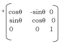
Suppose we want to rotate a point (x1 y1) clockwise through an angle? about the origin of the coordinate system. Then mathematically we can show that

x2 = x1cos ? + y1sin? and

y2 = x1sin? – y1cos?

These equations become applicable only if the rotation is about the origin.

In the matrix for [x2 y2 1] = [x1 y1 1]

              Matrix 1

Scaling : Suppose we want the point  (x1 y1)  to be scaled by a factor sx and by a factor sy along y direction.

Then the new coordinates become  : x2 = x1 * sx and  y2 = y1 * sy

                Matrix 2

(Note that scaling a point physically means  shifting  a point away.   It does  not   magnify

the  point.   But  when  a  picture  is  scaled, each  of  the  points  are  scaled differently  and  hence the dimensions of the picture changes.)

Difference between shadow mask and beam penetration method?

By Dinesh Thakur

Both methods are used in color CRT monitors. Beam penetration method is used for random scan monitors. In beam penetration two layers of phosphor red and green are coated inside CRT screen, the display of color depend on how far electron excites outer red layer, then green layer. This method can produce four colors i.e red ,green, orange, yellow. This is less costly method as compared to shadow mask.

 But it can produce less colors as compared to shadow mask. The quality of picture is also poor as compared to shadow mask. Shadow mask is used for raster scan systems. It can produce wide variety of colors .There is three phosphor color dots at each pixel position. One phosphor dot emit red light, another emit green light ,third emit blue light. Three guns one for each color are used. Three beams pass through holes in shadow mask, and a small color spot on screen is appeared. Shadow masks are used as display device for home computers, color tv set etc

Differentiate between raster scan and random scan displays.

By Dinesh Thakur

The most common form of graphics monitor employing a CRT is the raster scan display, based on television technology. In a raster scan system, the electron beam is swept across the screen, one row at a time from top to bottom. As the electron beam moves across each row, the beam intensity is turned on and off to create a pattern of illuminated spots. Picture definition is stored in a memory area called the refresh buffer or frame buffer.

This memory area holds intensity values for all the screen points. Stored intensity values are then retrieved from the refresh buffer and pointed on the screen one row at a time. Each screen point is referred to as a pixel.


When operated as a random scan display unit, the CRT has the electron beam directed only to the parts of the screen where a picture is to be drawn. Random scan monitors draw a picture one line at a time and for this reason are also known as vector displays. The component lines of a picture can be drawn and refreshed by a random scan system. A pen plotter operates in a similar way and is an example of a random scan, hard copy device.

What are the different techniques used for representing three-dimensional objects?

By Dinesh Thakur

The various techniques used are:


1) Graphics monitors for the display of three-dimensional scenes have been devised using a technique that reflects a CRT image from a vibrating, flexible mirror. In this system, as the mirror vibrates, it changes focal length.


These vibrations are synchronized with the display of an object on a CRT so that each point on the object is reflecting from the mirror into a spatial position corresponding to the distance of that point from a specified viewing position. This allows us to walk around an object or scene and view it from different sides.


2) Another technique for representing three-dimensional objects is displaying stereoscopic views. This method does not produce true three-dimensional images, but it does provide a three dimensional effect by presenting a different view to each eye of an observer so that scenes do appear to have depth. To obtain a stereoscopic projection, we first need to obtain two views of a scene generated from a viewing direction corresponding to each eye.


We can construct the two views as computer-generated scenes with different viewing positions, or we can use a stereo camera pair to photograph some object or scene. When we simultaneously look at the left view withy the left eye and the right view with the right eye, the two images merge into a single image and we perceive a scene with depth. Stereoscopic viewing is also a component in virtual reality systems, where users can step into a scene and interact with the environment.


A headset containing an optical system to generate the stereoscopic view is commonly used in conjunction withy interactive input devices to locate and manipulate objects in the scene. A sensing system in the headset keeps track of the viewer?s position, so that the front and back of objects can be seen as the viewer walks through and interacts with the display.

What are the various methods through which input is recorded in touch panels?

By Dinesh Thakur

1. Optical Touch Panel: Optical touch panels employ a line of infrared light-emitting diodes (LEDs) along one vertical edge and along one horizontal edge of the frame. The opposite vertical and horizontal edges contain light detectors. These detectors are used to record which beams re interrupted when the panel is touched.


The two crossing beams that are interrupted identify the horizontal and vertical coordinates of the screen position selected. Positions can be selected with an accuracy of about ¼ inch. With closely spaced LEDs, it is possible to break two horizontal or two vertical beams simultaneously. In this case, an average position between the two interrupted beams is recorded.


2. Electrical Touch Panel: An electrical touch panel is constructed with two transparent plates separated by a small distance. One of the plates is coated with a conducting material, and the other plate is coated with a resistive material. When the outer plate is touched, it is forced into contact with the inner plate. This contact creates a voltage drop across the resistive plate that is converted to the coordinate values of the selected screen position.


3. Acoustical Touch Panel: In acoustical touch panels, high-frequency sound waves are generated in the horizontal and vertical directions across a glass plate. Touching the screen causes part of each wave to be reflected from the finger to the emitters. The screen position at the point of contact is calculated from a measurement of the time interval between the transmission of each wave and its reflection to the emitter.

What is image processing? Explain its working principle.

By Dinesh Thakur

It is a technique to modify or interpret existing pictures, such as photographs. Two principal applications of image processing are:


1. Improving picture quality
2. Machine perception of visual information as used in robotics


Working of image processing: To apply image-processing methods, we first digitize a photograph or other picture into an image file. Then digital methods can be applied to rearrange picture parts, to enhance color separations, or to improve the quality of shading. An example of the application of image-processing methods is to enhance the quality of a picture. These techniques are used extensively in commercial art applications that involve the retouching and rearranging of sections of photographs and other artwork. Similar methods are used to analyze satellite photos of the earth and photos of galaxies.

Explain the line drawing algorithm for DDA.

By Dinesh Thakur

Digital Differential Analyzer is a scan conversion line algorithm based on calculating either dy or dx. We sample the line at unit intervals in one coordinate & determine corresponding integer values nearest to the line path for the other coordinate.

The algorithm accepts as input the two endpoint pixel positions. Horizontal & vertical differences between the endpoint positions are assigned to parameters dx & dy. The difference with the greater magnitude determines the increment of the parameter steps. Starting with the pixel position (xa , ya), we determine the offset needed at each step to generate the next pixel position along the line path. We loop through this process „steps? times. If the magnitude of dx is greater that the magnitude of dy & xa is less that xb, the values of the increments in the x & y directions are i & m. It is a faster method of calculating pixel positions. However, the accumulation of round off error in successive additions can cause the calculated pixel positions to draft away from the true line path for long line segments.


What are the various transformations possible in 2-D? Explain any 3 of them.

By Dinesh Thakur

1. Translation: A translation is applied to an object by repositioning it along a straight line path from one coordinate position to another. We translate a 2-D point by adding translation distances tx & ty, to the original coordinate position ( x, y) to move the point to a new position (x? , y?)
X? = x + tx , y? = y + ty.


2. Rotation: A 2-D rotation is applied to an object by repositioning it along a circular path in the xy plane. To generate a rotation, we specify a rotation angle ? and the position (xr , yr) of the rotation point about which the object is to be rotated.
P1 = R . P
Where the rotation matrix is R = cos? – sin ? sin ? cos?


3. Scaling: A scaling transformation alters the size of a.n object. This operation can be carried out for polygons by multiplying the coordinate values (x,y) of each vertex by scaling factors sx & sy to produce the transformed coordinates (x? , y?):
x1 = x.sx , y1 = y.sy

4.Reflection: It is also called as mirror or mirror image . It can be either about x axis or y axis. The object is rotated about 180 degree. Reflection can be done about line.


5. Shearing : It is change of shape of object. It can be in x or y or both directions.

What is clipping? Explain any one clipping algorithm.

By Dinesh Thakur

Any procedure that identifies those portions of a picture that are either inside or outside of a specified region or space is known as clipping. [Read more…] about What is clipping? Explain any one clipping algorithm.

Sutherland-Hodgeman Polygon Clipping

By Dinesh Thakur

In polygon clipping, we use an algorithm that generates one or more closed areas that are then scan converted for the appropriate area fill. The output of a polygon clipper should be a sequence of vertices that define the clipped polygon boundaries. We can correctly clip a polygon by processing the polygon boundary as whole each window edge.

This could be accomplished by processing all polygon vertices against each clip rectangle boundary in turn. Beginning with the initial set of polygon vertices, we could first clip the polygon against the left rectangle boundary to produce a new sequence of vertices. The new set of vertices could then be successively passed to a right boundary clipper and a top boundary clipper. There are four possible cases when processing vertices in sequence around the perimeter of a polygon.


As each pair of adjacent polygon vertices is passed to a window boundary clipper, we make the following tests:


1) if the first vertex is outside the window boundary and the second vertex is inside, both the intersection point of the polygon edge with the window boundary and the second vertex are added to the output vertex list.


2) If both input vertices are inside the window boundary, only the second vertex is added to the output vertex list.


3) If the first vertex is inside the window boundary and the second vertex is outside, only the edge intersection with the window boundary is added to the output vertex list.


4) If both input vertices are outside the window boundary, nothing is added to the output list.

Write a note on text clipping.

By Dinesh Thakur

There are several techniques that can be used to provide text clipping in a graphics package. The clipping technique used will depend on the methods used to generate characters and the requirements of a particular application.

The simplest method for processing character strings relative to a window boundary is to use all-or-none string-clipping strategy. If all of the string is inside the clip window, we keep it. Otherwise, the string is discarded. This procedure is implemented by considering a bounding rectangle around the text pattern. The boundary positions of the rectangle are then compared to the window boundaries, and the string is rejected if there is any overlap. This method produces the fastest text clipping.  

An alternative to rejecting an entire character string that overlaps a window boundary is to use the all-or-none character-clipping strategy. Here we discard only those characters that are not completely inside the window. In this case the boundary limits of individual characters are compared to the window. Any character that either overlaps or is outside a window boundary is clipped.
A final method for handling text clipping is to clip the components of of individual characters. We now treat characters in much the same way that we treated lines. If an individual character overlaps a clip window boundary, we clip off the parts of the character that are outside the window.

What is half-toning effect?

By Dinesh Thakur

Continuous-tone graphs are reproduced for publication in newspapers, magazines & books with a printing process called half toning, & the reproduced pictures are called halftones. For a black and white photograph, each intensity area is reproduced as a series of black circles on white background.

 The diameter of each circle is proportional to darkness required for that intensity region. Darker regions are printed with large circles , Lighter regions are printed with small circles. Books and magazine are printed on high quality paper using 60 to 80 circles of varying diameter per centimeter. Newspaper use lower quality paper and lower resolution.

What is Ambient Light?

By Dinesh Thakur

A surface that is not exposed directly to a light source still will be visible if nearby objects are illuminated. In our basic illumination model, we can set a general level of brightness for a scene. This is a simple way to model the combination of light reflections from various surfaces to produce a uniform illumination called the ambient light, or background light.

Ambient light has no spatial or directional Characteristics. The amount of ambient light incident on each object is a constant for all surfaces and over all directions.

Primary Sidebar

Computer Graphics Tutorials

Computer Graphics

  • CG - Home
  • CG - Introduction
  • CG - Applications
  • CG - Applications
  • CG - Raster Vs Random Scan Display
  • CG - Frame Buffer
  • CG - DVST
  • CG - CRT Display
  • CG - DDA
  • CG - Transformation
  • CG - Cathode Ray Tube
  • CG - Bresenham’s Line Algorithm
  • CG - Pixel
  • CG - Data Compression
  • CG - Clipping
  • CG - Shadow Mask CRT
  • CG - Line Drawing Algorithm
  • CG - Text Clipping
  • CG - Refresh Rates
  • CG - CRT/Monitor
  • CG - Interactive Graphics Display
  • CG - Raster Vs Random Scan System
  • CG - Liquid Crystal Display
  • CG - Scan Converting a Line
  • CG - Monitors Types
  • CG - Display Types
  • CG - Sutherland-Hodgeman Clipping
  • CG - Bitmap
  • CG - Antialiasing
  • CG - Refresh Rates
  • CG - Shadow Mask Vs Beam Penetration
  • CG - Scan Converting a Point
  • CG - Image Resolution
  • CG - Double Buffering
  • CG - Raster Vs Random Scan
  • CG - Aspect Ratio
  • CG - Ambient Light
  • CG - Image Processing
  • CG - Interactive Graphics Displayed
  • CG - Shadow Mask CRT
  • CG - Dithering
  • CG - GUI
  • CG - CLUT
  • CG - Graphics
  • CG - Resolutions Types
  • CG - Transformations Types
  • CG - Half-toning Effect
  • CG - VGA
  • CG - Aliasing
  • CG - CGA

Other Links

  • Computer Graphics - PDF Version

Footer

Basic Course

  • Computer Fundamental
  • Computer Networking
  • Operating System
  • Database System
  • Computer Graphics
  • Management System
  • Software Engineering
  • Digital Electronics
  • Electronic Commerce
  • Compiler Design
  • Troubleshooting

Programming

  • Java Programming
  • Structured Query (SQL)
  • C Programming
  • C++ Programming
  • Visual Basic
  • Data Structures
  • Struts 2
  • Java Servlet
  • C# Programming
  • Basic Terms
  • Interviews

World Wide Web

  • Internet
  • Java Script
  • HTML Language
  • Cascading Style Sheet
  • Java Server Pages
  • Wordpress
  • PHP
  • Python Tutorial
  • AngularJS
  • Troubleshooting

 About Us |  Contact Us |  FAQ

Dinesh Thakur is a Technology Columinist and founder of Computer Notes.

Copyright © 2025. All Rights Reserved.

APPLY FOR ONLINE JOB IN BIGGEST CRYPTO COMPANIES
APPLY NOW