• Skip to main content
  • Skip to primary sidebar
  • Skip to secondary sidebar
  • Skip to footer

Computer Notes

Library
    • Computer Fundamental
    • Computer Memory
    • DBMS Tutorial
    • Operating System
    • Computer Networking
    • C Programming
    • C++ Programming
    • Java Programming
    • C# Programming
    • SQL Tutorial
    • Management Tutorial
    • Computer Graphics
    • Compiler Design
    • Style Sheet
    • JavaScript Tutorial
    • Html Tutorial
    • Wordpress Tutorial
    • Python Tutorial
    • PHP Tutorial
    • JSP Tutorial
    • AngularJS Tutorial
    • Data Structures
    • E Commerce Tutorial
    • Visual Basic
    • Structs2 Tutorial
    • Digital Electronics
    • Internet Terms
    • Servlet Tutorial
    • Software Engineering
    • Interviews Questions
    • Basic Terms
    • Troubleshooting
Menu

Header Right

Home » Electronics » Digital

What is Capacitor (C)? – Definition

By Dinesh Thakur

Definition: Capacitor or Condenser is an insulating medium that can separate two conducting surfaces.The insulating medium is called dielectric constant or relative permittivity of the material. Most commonly used dielectric materials in the capacitor are air, mica, and paper, ceramic, plastic.

This insulating medium does not allow the DC current to pass through the condenser whereas, in an AC circuit, the current flows through the capacitor with little or no resistance.

The capacitor is an electrical component which can store energy in the form of an electrical charge.

Capacitor

Types of Capacitor

The different types of capacitor are as follows:

Dielectric Capacitor

It is of variable type and required for tuning transmitters, receivers, and transistor radios. These dielectric capacitors are multi-plate which have a set of both fixed plates and movable plates. The movable plates move in between the fixed plates.

Film Capacitor

These are most commonly available among all types of capacitor. Film capacitors consist of a family of capacitors, but their dielectric properties are different. The dielectric material may include polyester, Teflon, metalized paper.
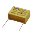
Film capacitor

Ceramic Capacitor

Ceramic capacitors are made by coating the two sides with silver and then stacked together to create a capacitor. Ceramic capacitors are also known as Disc Capacitors.
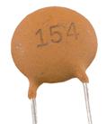
Ceramic capacitor

Electrolytic Capacitor

This type of capacitor used when a considerable capacitance value is needed. Here, the semi-liquid electrolyte solution in the form of a paste used.
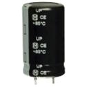
Electrolytic capacitor

These used in DC power supply circuits. Electrolytic capacitors have two forms:

Aluminum Electrolytic Capacitors

These are of further two types: Plain foil type and etched foil type. The DC current was anodized to the foil plates of the capacitor, and because of this anodizing process, the polarity of the poles can be set up, and this contradiction tells us that which side of the plate is positive or negative.

Also, they have the ability of re-anodizing the foil plate. If the layer of aluminum oxide destroyed, then the electrolytic capacitor would allow the current to pass through the condenser and destroys the capacitor.

Tantalum Electrolytic Capacitors

This type of capacitor is available in both wet and dry electrolytic types. The dry electrolytic capacitor most commonly used. They mostly used in those circuits where the AC voltage is small as compared to the DC voltage.

The factors on which capacitance of a conductor depends

The capacitance of a conductor depends on the following factors:

Size of the plates: Larger the size of the plates, the higher the charge they can hold for a given potential and hence higher the capacity.

Distance between the plates: The capacitance of a capacitor depends upon the distance between the plates. The smaller the length, more the capacitance and vice-versa.

Relative permittivity: The capacitance of a capacitor depends upon the relative permittivity of the insulating medium. Greater the relative permittivity, higher the capacitance and vice-versa.

Capacitor Characteristics
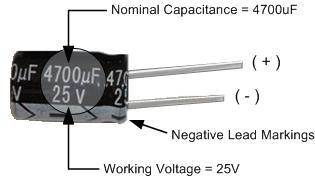
Capacitor characteristics

Normal capacitance(C): The standard value of capacitancemeasured in picofarads (pF), nano-Farads (nF) or micro-Farads. The capacitance of a capacitor can change value according to the frequency of the circuit.

Working voltage: The working voltage is the maximum voltage, whether it is AC or DC, which can apply to the circuit without breaking its entire working life.

Tolerance (+-%): Capacitors have a tolerance rating, which represented in plus or minus value either in Pico-farads for the capacitors whichhave low value or in percentage for the capacitors which has a higher value. The most common tolerance variation is 5% or 10%.

Leakage current: The dielectric medium which we used to separate the plates of the capacitor is not the perfect one, and there is a leakage of current. This small leakage of current is known as Leakage Current.

Working temperature: As we know, the change in temperature allows the change in dielectric properties. So the difference in temperature affects the capacitance also. The average working range for most of the capacitors is -30C to +125C.

Temperature coefficient: The temperature coefficient of a capacitor told us about the maximum change in its value of capacitance for a specified temperature rangeandexpressed as parts per million degrees per centigrade.

Polarization: Capacitor polarization tells us about the electrolytic type capacitors, and they must have the right polarity. As we know incorrect polarization, can damage out the circuit.

Equivalent series resistance: It is the AC impedance of the capacitor. It tells us about the energy losses of the equivalent series resistance of a capacitor.

Grouping of Capacitor

The capacitor can connect in the following ways:

Capacitors in Series

The capacitors are said to be connected in series when the same charge exists on all the capacitor plates. The total capacity of the series grouping can be found out by the formula:
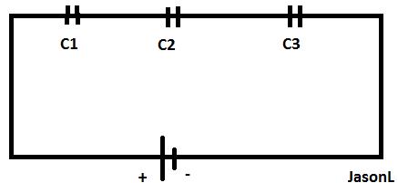
Capacitors in series

Hence, when the number of capacitors connected in series, the reciprocal of the total capacitance is equal to the reciprocal of individual capacitance.

total capacitance of parallel grouping formula

Capacitors in Parallel

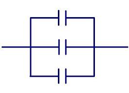
Capacitors in parallel

The capacitors are said to be connected in parallel when one plate of each capacitor connected to a common point and the other plate of each capacitor connected to the other standardend in such a way that the potential difference across each capacitor is the same.

The total capacitance of the parallel grouping can be found out by the formula:

total capacity of the series formula

Hence, when some capacitors connected in parallel, then the total capacitance is equal to the sum of individual capacitance.

Capacitors in Series-Parallel
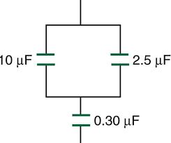
Capacitors in series-parallel

When some capacitors connected in parallel, are connected in series with the other capacitors, then the grouping is said to be in the series-parallelcluster.

For finding out the total capacitance of series-parallel grouping, first, find out the equivalent capacitance of the parallel combination and then the circuit reduced to the series circuit.

Applications of Capacitor

• The capacitor used for the storage of energy.

• Energy storage in capacitors is used to construct dynamic digital memories.

• Reservoir capacitors used in power supply.

• The capacitor also used for many pulsed power applications like lasers, radar, pulse forming networks.

• The capacitors also used for power factor correction.

• They are used to separate AC and DC components because capacitors pass AC and block DC.

• The energy stored in a capacitor is also used to represent information.

• Radio receivers use variable capacitors for tuning of frequency.

What is Resistance? – Definition

By Dinesh Thakur

Definition: Resistance (Represented by R) offers hindrance to the flow of current in an electrical circuit. It is measured in ohms, which is named after its developer George Simon Ohm. He is a German physicist, who has studied the relationship between voltage, current and resistance and tells us that when one volt of voltage is applied across the component and one ampere of current is passed through it, then the resistance offered by that component is one ohm. The symbol used for resistance is the Greek letter omega (Ω).

The resistance of an object can be stated as the ratio of the potential difference applied across the terminal to the current applied.

                                                             R=V/I

Here you can also say that current is inversely proportional to the resistance, i.e. when the current in the circuit gets doubled, then the resistance offered is half and if the resistance is doubled, then the current applied is half.

All materials resist the flow of current. So they can be categorized into two broad terms:

Conductors: These are those materials which offer very less resistance and electrons can move easily in the substance.

Ex:- copper (Co), silver (Ag), Gold (Au) etc.

Insulators: these are those materials that offer high resistance to the substance and electrons do not able to move easily or it resists the flow of electrons.

Ex: rubber, wood, plastic etc.

Laws of Resistance

The resistance of a substance depends upon the four factors- length, cross-sectional area, the nature of the material and the temperature of the substance.

The resistivity or specific resistance can be measured from the 4 laws of resistance which are as follows:

1st law of Resistance

This law states that resistance is directly proportional to the length of the substance or you can say that when the length of the substance increases, then its resistance also increases and when the length of the substance decreases, then its resistance also decreases. The reason behind this is when the length gets increased, then the electrons will travel more paths and the chances of collision get increased and as a result, the number of electron passing through the conductor get reduced, thus, the current is reduced. It can also be written as

                                                                  1st law of resistance

Where L is the length of the conductor

2nd law of Resistance

This law states that the resistance of a conductor is inversely proportional to the area of cross-section. It can also be written as

                                                                     2st law of resistance

Where ‘A’ is the area of cross-section.

You can say that if the area of cross-section is more, then more electrons will pass, which causes more current through the conductor which means that less resistance is offered. Thus, when an area of cross-section is more, then there is less resistance and vice-versa.

After combining 1st two laws, the resistance can be written as

                                                                2st law of resistance

Where ρ is the constant of proportionality and is called as specific resistance or resistivity. The letter ρ is pronounced as rho.

3rd law of Resistance

The resistivity of all materials is not same. The relationship between resistivity and resistance is direct proportionality, i.e. if the resistivity of the material is large, then the resistance offered by the material is also more and vice-versa is also true.

                                                                  3st law of resistance

4th law of Resistance

This law also states that the temperature of the substance will affect the resistance offered by the substance. As we know that, more temperature causes more vibration between electrons because the electrons will gain energy and become excited, which leads to the great obstruction among electrons? So here we can say that as the temperature increases, the resistance offered by the substance also increases and vice-versa.

what is diode | diode definition

By Dinesh Thakur

Definition: A diode is an electronic component that allows the flow of current in only one direction and when the current flows in the other direction, then it blocks the current. The name diode is derived from the word “di-ode” which means that a device having two electrodes. Thus, a diode has two electrodes one electrode is known as the anode and the other electrodes are known as the cathode.

The diode is a semiconductor device, which is usually made from silicon, germanium, or selenium, that is classed as intrinsic semiconductors. Diodes are widely used as a rectifier, signal modulators, signal demodulators, voltage regulators, signal mixers, signal modulators, signal limiters etc.
The fundamental Diodes allow current to flow in only one direction and also change the electrical current from alternating current (AC) to direct current (DC), the process of conversion is known as rectification. The diode will start operating only when a voltage is applied across its terminals. The ‘ON’ state of a diode is achieved when the positive point is applied to the anode and negative point is applied to the cathode or you can say that the ‘ON’ state of a diode has current is in the direction of the arrowhead. This procedure is known as ‘Forward biasing’. Similarly, the ‘OFF’ state of a diode is achieved when the lower potential is applied to the anode and higher potential is applied to the cathode or you can say that the ‘OFF’ state of a diode have current in the opposite direction of the arrowhead. This procedure is known as ‘Reverse biasing’.

diode symbol

Types of Diode

There are many types of diode that are available which are listed as follows:

Backward Diode

It is also known as a back diode. It is least used diode. The process of the backward diode is similar to the tunnel diode. It can be used in some applications where it is needed.

Backward diode symbo

Gunn Diode

It is a PN Junction diode and it is similar to the semiconductor device which has two terminals. It is also known as Transferred Electronic Device. This diode is used to generate microwaves.

Laser Diode

It does not resemble with the ordinary LED (Light Emitting Diode) as it generates coherent light. This type of diode is used in many applications like CD drives, DVD drives etc. Also, these diodes are less costly as compared to other diodes.

Photo Diode

This type of diode is used to detect light. It can also be used to produce electricity. Generally, these types of diodes used to operate under reverse bias condition.

Pin Diode

This type of diode is one of the types of the photodetector which is used to convert the optical signal into an electrical signal. This diode consists of three regions-
P-region, I-region, and N-region, whereas both P and N-region are heavily mixed with impurities and the I-region have no mixed impurity.

Pin diode

PN Junction Diode

This type of diode is in use nowadays. The PN junction diode is a two-terminal device. This type of diode is formed when one side of the PN junction diode is made up of p-type and is mixed with the n-type material. PN junction diode is used in low current applications.

BARITT Diode

The full form of BARITT is Barrier Injection Transmit Time diode. This type of diode is used for the generation of the microwave signal, burglar alarm etc.

Light Emitting Diodes

The short form of the Light emitting diode is LED which is most commonly used. These LEDs contain a semiconductor chip and LEDs can produce many colors, but the most common color is red.

Zener Diode

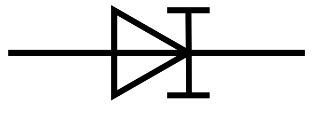
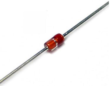
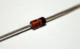
Zener diode operates in reverse bias condition i.e. when a particular voltage is reached, then the circuit gets to break down. This type of diode is used to provide a stable reference voltage. Generally, this type of diode is used to provide a reference voltage during the supply of the power.

Zener diode

Tunnel Diode

It is not most commonly used. A tunnel diode is also called as Esaki diode as it is invented by Leo Esaki. It is mainly used in the microwave applications. Tunnel diode can also be used as an amplifier, oscillators and in any switching circuits.

Step Recovery Diode

This type of diode is used to generate at the very high frequency.

Schottky Diode

This type of diode is designed in a different way as compared to other diodes. Also, Schottky diodes have a lower forward voltage drop. Generally, they are used as clamping diodes.

Varactor Diode

This type of diode is also known as varicap diodes and it is mainly used in radio frequency applications. Varactor diodes are designed in such a way that they permit a high range of changes in capacitance.

Applications of Diode

• The diode is used in the rectifier.
(Rectification is the process of converting AC (Alternating Current) into DC (Direct Current).
• Diodes are used in clipper circuit.
(Clippers are the networks in which we make use of diodes to “clip” away a portion of an input signal without affecting the other part of the applied waveform)
• Diodes are used in clamper circuit.
(A clamper is a network which is made up of a diode, a resistor, and a capacitor.  It shifts the waveform to an another DC level without affecting the applied signal.)
• Laser diodes are used in medical treatment like cancer detection, DNA analysis, blood analysis, X-ray film marking etc…
• LEDs are used in household appliances, switches, security equipment, mobile phones, Digital cameras, laptops etc.

Advantages of using a Diode

• It is more suitable for pulsed operation.
• There is very low power dissipation for diodes.
• Their efficiency is high.
• They allow the flow of current in only one direction.
• An ideal diode has zero resistance in the forward direction and infinite resistance in the opposite direction.
• They are small and compact.
• They are more reliable.

Direct Sequence Spread Spectrum – DSSS

By Dinesh Thakur

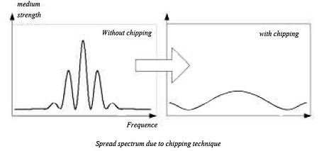
The DSSS (Direct Sequence Spread Spectrum) is a technique spread spectrum, but unlike the FHSS, no frequency hopping is place: DSSS causes very rapid state transitions (chipping) which tend to spread the spectrum of the signal: in fact, we have seen that with the modulations FSK, PSK and QAM width of the spectrum was twice the rate of the source. Causing “artificially” very high throughput, spectrum is spread.

To do this, the transmitter sends a sequence of several bits, called chips, for each information bit to be transmitted. For example, we may choose to send 11101 instead of 0 and its inverse (00010) instead of one: in this case, if one wants to transmit information 010, then we will issue the following chips: 11101 00010 11101. In this example, the 11101 sequence is called the “spreading code”. Over this code, the longer the flow is artificially multiplied, so more spectrum is spread. For example, if the flow of data to be sent is 1 Mb / s, but we uses a spreading code of 11 chips, then the chips flow will of course be equal to 11 Mb / s: suddenly, the frequency band occupied by the signal will have a width equal to 22 MHz because the width of the band occupied by the signal is equal to twice the speed of source. Without chipping the occupied band would have only a width of 2 MHz (two After 1 Mb/s).

Direct Sequence Spread Spectrum

DSSS has two important interests:

• First, as we have said, the signal spectrum is spread, with all the advantages (and disadvantages) that this brings, especially better resistance to noise;
• in that it emits several chips for each bit of information means that can have a significant redundancy that corrects errors transmission. For example, in the previous example, since the receiver knows the spreading code used (11101) then he knows he should receive than 11101 (for the information bit 0) or 00010 (for bit 1). If it receives 00110, it can easily correct the error in considering that the nearest is 00010 (corresponding to bit 1).

802.11 identified fourteen channels of 22 MHz wide, in the same strip of frequencies in the 2.4 GHz FHSS. To communicate, the transmitter and receiver must agree on a fixed channel to use. A flow rate of 1 Mb / s, the 802.11 DSSS modulation based on 2DPSK we saw the 2 Mbit / s DSSS simply uses the 4DPSK modulation.

In both cases, the spreading code has a length of 11 bits and it is always equal to 10110111000. This code is part of a family of codes to mathematical properties Similar defined in 1953 by the mathematician Barker: they promote a good spread spectrum (as would not do, for example, the code 11111111111) and format makes them well suited to synchronize the transmitter and the receiver, which limits problems due to multipath.

CCK modulation

To achieve data rates of 5.5 Mb / s or 11 Mb / s, the further improved the 802.11b process using the modulation Complementary Code Keying (CCK) to reach the so-called high-speed or high-rate DSSS DSSS (HR-DSSS). This one still based on the same basic principle spreading by chipping with 4DPSK modulation. However, instead of always using the same code for Barker spread the signal, it uses up to 64 different codes, which can be transported 6 information bits (because 26 = 64) in addition to the two bits allowed by the modulation 4DPSK. These codes of 8 bits in length each, are “complementary codes” that is to say, their mathematical properties allow receivers not confused, even if there is some transmission errors and even an offset in the reception due to multipath. Since there is significantly less redundancy, it gets more flow, at least as good reception (so short distance). Since the resistance to multipath is better, HR-DSSS is best suited for indoor and short distances on the DSSS Barker.

Unfortunately, when the FHSS can jump congested channels of noise or interference, DSSS can not: If there are other wireless networks operator near the same channel, DSSS will suffer greatly. knowing that Bluetooth technology is based on the FHSS on the same frequencies to 2.4 GHz we understand why the 802.11 DSSS suffers from the presence of Bluetooth devices near. However, Bluetooth support about the presence of equipment 802.11 DSSS. To summarize, the DSSS supports more homogeneous noise (noise “White”) that the FHSS and vice versa, the FHSS better support focused noise on a particular frequency as the DSSS.

As with FHSS, the standard defines for the DSSS a coping mechanism automatic flow depending on the distance. Thus, short modulation HR-DSSS will be 11 Mb / s (8-bit information to 8 chips issued). Moreover, further, one automatically to 5.5 Mb / s (4 bits of information for 8 chips issued). Then, down to 2 Mb / s using the DSSS / 4DPSK Barker and then to 1 Mb / s DSSS / Barker and 2DPSK.

Frequency Hopping Spread Spectrum (FHSS)

By Dinesh Thakur

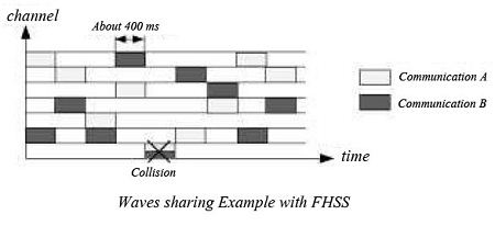
The FHSS (Frequency Hopping Spread Spectrum) was invented and patented in 1942 by the actress Hedy Lamarr and pianist George Antheil, which were quite versatile! The principle of FHSS is quite simple: a wide frequency band is divided into multiple channels and communications are jumping (hopping) sequentially from one channel to another in a sequence and a rate agreed to advance between the transmitter and the receiver.

It is difficult to intercept communications if we do not know the sequence chosen, so it was much appreciated by the US military who used for radio guide torpedoes without the enemy to intercept or jam the signal. In the case of 802.11, this function is (unfortunately) not operating because the channel sequences used are not secret.
FHSS also provides significant resistance to interference or even volunteers for interference channels where the noise is too large can simply be avoided. However, 802.11 FHSS does not exploit this ability, unlike Bluetooth and Home RF are two technologies Wireless using FHSS modulation.
A final advantage is that many of the FHSS communications may held simultaneously on the same frequency band as long as they use channel sequences not colliding with each other. For example, communication could use the trivial sequence 1,2,3,1,2,3,1,2,3 while … another communication would have the following sequence: 2,3,1,2,3,1,2,3,1 … so at no time did the two communications using the same channel.
In return, each communication has a relatively low rate since operates only one fairly narrow channel at a time.
In the first version of 802.11, the frequency range from 2400 MHz 2483.5 MHz was cut for the FHSS channels of 1 MHz wide each.

        Frequency Hopping Spread Spectrum
In most countries, the channels 2-80 are allowed (from 2401 MHz to 2480 MHz). Within each channel, modulation Gaussian FSK with two states (2GFSK) is used and allows a flow rate of 1 Mb/s. Using 4GFSK modulation (GFSK four states, or 2 bits per symbol) you can reach 2 Mb / s. Using GFSK as a modulation underlying FHSS avoids interference between neighboring channels, allowing multiple users to communicate in FHSS same time without interfering.
802.11 has defined a dynamic rate adaptation mechanism Depending on the signal / noise ratio: When high, the modulation used is 4GFSK to 2 Mb / s, otherwise the 802.11 adapts automatically and “down” in 2GFSK 1 Mb/s.

Type of Radio Modulations

By Dinesh Thakur

The basic modulations

No modulation

Take the example of an opera broadcast on a radio station: how music, that is to say, an audio signal, it may be channeled through wave electromagnetic? Audible sound waves have frequencies between 20 Hz to 20 kHz for bass and treble. It would be tempting to simply convert the sound wave in radio waves of the same frequency. Unfortunately, there would be several problems: first, the low radio frequencies also are very difficult to produce and capture; then two simultaneous radios would overlap since they would be issued on the same frequency band (20 Hz to 20 kHz) and would cacophony. [Read more…] about Type of Radio Modulations

What is Boolean Logic?

By Dinesh Thakur

This was first created by an English mathematician named George Boole in 1847 and yet, in one of the strange quirks of the computer industry, is now used in everything from circuit design to searching the Internet. In essence Boole developed a system for reducing complex questions into simple yes or no answers by using what are known as truth tables, sometimes called gates.

Although these truth tables or gates can take several forms the three that are relevant to Internet searches are AND, OR and NOT. Each one operates differently.

and

This produces an output only if two specified conditions are met. For example if a search was made on the words ‘Economic’ AND ‘Policy’ the truth table would be as follows:

1st Condition            2nd Condition               Output

(Economic)           (Policy)

NO                            NO                                           NO

YES                          NO                                           NO

NO                            YES                                         NO

YES                          YES                                         YES

Only if both words were found on the same website would a match be returned.

or

This produces an output if either specified condition is met. In the same example as above the truth table would be:

1st Condition        2nd Condition                  Output

(Economic)           (Policy)

NO                              NO                                            NO

YES                            NO                                            YES

NO                              YES                                          YES

YES                            YES                                           YES

If either word is found on a website a match would be returned.

not

This returns an output only if a specified condition is not met. To continue the above example if a search was made on the words ‘Economic’ NOT ‘Policy’ the truth table would be:

1st Condition             2nd Condition               Output

(Economic)                (Policy)

YES                                  YES                                       NO

NO                                    YES                                       NO

YES                                   NO                                        YES

NO                                     NO                                        NO

Only websites which contain the word ‘Economic’ but do not contain the word ‘Policy’ will be returned.

In electronics the output from one set of gates can become the input to others to produce complex switching arrangements which forms the basis of the computer microchip itself. Away from that it is by combining these various logical operators (as AND, OR and NOT are known) that highly precise Internet searches can be conducted, as will soon become clear.

What is MOSFET (Metal Oxide Semiconductor Field- Effect Transistor)?

By Dinesh Thakur

(Metal Oxide Semiconductor Field- Effect Transistor) The fundamental building block of modern VLSI chips such as microprocessors and memory chips. A microscopically small FIELD-EFFECT TRANSISTOR formed on the surface of a prepared silicon wafer by exposing it to a succession of chemical treatments through a sequence of masks.

Each transistor consists of a GATE formed from POLYSILICON separated by a thin layer of silicon oxide insulation from the underlying DIFFUSION LAYER in which the SOURCE and DRAIN are formed by DOPING the silicon surface.

Thin tracks formed in a final metal layer (of aluminium or copper) join all these transistors together to form a complex electronic circuit.

What is Flip-flop?

By Dinesh Thakur

A digital logic circuit that can store a single BIT of information, and is therefore used as the basis for the construction of MEMORY chips, LATCHES and the REGISTERS within processors. A flip-flop can exist in two states, with either a high or low voltage at its output, and flips from one state to the other at each pulse of a CLOCK SIGNAL. Two different implementations of flip-flop are commonly used, called the D flip flop and the j-K flip flop.

What are DIP switches?

By Dinesh Thakur

DIP switches are those nasty, tiny plastic toggle switches that come mounted together in a row on a little box-like part attached to your computer’s motherboard or on some of your add-in boards. Each individual switch in a DIP switch unit can be set either on or off, allowing you to control some aspect of your computer’s function. For example, on the older IBM pcs and compatibles, you had to set the DIP switches to match the amount of memory installed in your computer, to tell it what kind of monitor you had, and so on. On the add-in modem board I just installed, I had to flip some of the DIP switches so the computer would know where to find the board electronically.


DIP switches are a monumental pain. For one thing, they’re so small it’s hard to switch them. Use the tip of a ballpoint pen, an unfolded paper clip, a baby screwdriver blade, or some other fairly pointy, narrow tool. Worse yet, they’re always mounted in some out-of-the-way place, like on the back of your computer or inside it. Even if you can get to the switches without opening up the computer, you have to pull the machine out from the wall as far as it will go, cram your head back there, and just hope you’ll switch the right switch. And the labels that tell you which direction is on or off are horrible. The writing is too small to see, and usually it says 1 and 0 instead of ON and OFF (yes, 1 [one] means on, 0 [zero] means off).

The point is, if two products are otherwise equal in features and price, choose the one that doesn’t have DIP switches. It will set itself up automatically, or maybe it comes with a software utility that lets you set it up by choosing options on your computer screen. 

What is DIP (dual inline package)?

By Dinesh Thakur

DIP is an acronym that stands for dual inline package and refers to the physical layout of most computer chips. The standard chip looks like a bug, or a little rectangular box with legs. Those two rows of metal legs are the “pins” that connect the chip to the computer’s circuits. The whole chip is referred to as a “package,” and it’s a dual inline package because the pins are lined up in two rows. 

What is chip?

By Dinesh Thakur

A chip is that truly amazing and remarkably tiny piece of silicon that has an entire integrated electronic circuit embedded within it. Chips are what make the computer. Chips are the computer. A tiny chip is one of the biggest pieces of human-made magic on earth. There are different kinds of chips, the most common being the microprocessors which run the whole computer, and memory chips, in which the computer holds and works with your information until you send it to a disk.

The chip that runs many pcs, the 80486, has the equivalent electronic power-in its baby-fingernail sized wafer-of one of those room-sized mainframe computers from twenty years ago. The 80486 can be manufactures for just a couple hundred dollars; the mainframes of twenty years ago cost several million dollars. The impact on civilization and humankind of this mass-produced, inexpensive technology is going to be comparable to the impact of the technology of mass-produced, inexpensive books in the fifteenth century.

What is breadboard?

By Dinesh Thakur

A breadboard is a thin board, sometimes fiberglass and sometimes plastic, with lots of little holes arranged in a grid. Electronics engineers use breadboards to create prototypes of circuit boards by wiring chips, resistors, and other electronic parts onto the board by hand, with the connecting wires running underneath. The term sometimes refers to the finished prototype itself, but more often it’s applied to the hole-filled board to which the electronic components are attached.

What is Boolean expression or Boolean logic?

By Dinesh Thakur

Boolean logic A formal logic system derived from the BOOLEAN ALGEBRA by interpreting its two permissible values 0and 1 as the TRUTH VALUES True and False. It is used in electronics to define the behavior of all the kinds of LOGIC GATE from which computer processors are constructed, and in programming to define operators that work on truth-valued variables.

It’s used to solve the kind of problems you buy a database program to handle: like, “show me the list of men who dance, and who cook or like washing dishes, and who are not married.” (Boolean logic is big on expressions such as and, or, and not.) You use Boolean logic every time you search your database. Boolean logic comes in very handy on a digital computer (which is what you have) because each answer can be a bit that is either on or off, true or false. The computer uses Boolean logic in a great deal of its work.

What is analogue-to-digital converter?

By Dinesh Thakur

Analogue-to-digital converter (AID converter, ADC) An important type of electronic circuit that inputs an ANALOGUE signal and outputs a stream of bits that reproduces that input signal in the digital domain. Conversion involves sampling the strength of the input signal at very short intervals and expressing the sampled value as a binary number. ADCs are widely employed in electronic equipment of many kinds, including digital cameras and camcorders, telephones and MODEMS, and the SOUNDCARDS used in personal computers.

The two most important parameters in describing an ADC are the size (in bits) of the samples it takes, and how many samples it takes per second.

For example to digitize an analogue microphone signal at CD quality requires an ADC capable of taking 44 million 16-bit samples per second.

What is analogue or analog?

By Dinesh Thakur

1. A physical object or quantity, for example a moving clock hand or an electrical voltage, that is used to measure or represent some other quantity, and is hence analogous to it.

2 A family of electronic devices that represent other physical quantities by continuously varying voltages rather than the two discrete voltage levels used in DIGITAL devices.

For example the output voltage of an analogue microphone follows exactly the changes in sound pressure of a speaker’s voice. All telephone, radio and television systems prior to the 1990S were based on analogue electronics.

The disadvantage of analogue devices compared to digital ones is that any physical effect that changes the voltage – such as non-linearity in the conductors, stray electrical or magnetic fields, power supply fluctuations – will corrupt the data. The advantage of analogue devices is that they may operate faster than digital devices, or store data more densely, since they avoid the overheads incurred in digitizing the data.

What are Amplitude and Amplitude modulation?

By Dinesh Thakur

Amplitude Size, magnitude, extent. When used of a WAVEFORM it refers to the height of the wave, measured from top to bottom of the following trough.

Amplitude modulation: The transmission of information by altering the magnitude of the successive cycles of a CARRIER wave, as opposed to FREQUENCY MODULATION where it is the spacing of successive cycles that encodes the information.

What is amplifier?

By Dinesh Thakur

An electronic circuit that increases the amplitude of its input signal and outputs the result. The most familiar type is the audio amplifier, as found in domestic hi fi or telephones, but amplifiers are to be found in every sort of device, including silicon chips:

for example there is a microscopic amplifier in each of the thousands of cell rows on a RAM chip.

What is alternating current (AC)?

By Dinesh Thakur

An electrical current that periodically reverses its direction. The electrical mains supply is an alternating current that varies in a sinusoidal fashion, reversing itself 50 times per second in the UK and Europe, and 60 times per second in the USA.

Digital signals are SQUARE-WAVES that do not actually change direction, but switch between, for example 0 and 5 volts; in their electrical properties, however, they behave more like alternating currents than DIRECT CURRENTS.

What is analog-to-digital conversion (ADC)?

By Dinesh Thakur

A-to-D conversion (analog-to-digital conversion) is the process of converting analog information from life into digital information that a computer can understand. Most information in nature is in analog form, covering a continuous range of values (such as the passing of time, as exemplified by the hands of a regular clock).

Digital information is in discrete, or separate, values, such as the countable chunks of seconds and minutes in a digital clock. You might want to use a computer to record analog information from nature by hooking it up to some kind of sensor like a light or pressure meter. But to store this information in the computer, the analog readings from these meters must be passed through an A-to-D converter to turn them into a digital form.

What is 8088,8086,80186?

By Dinesh Thakur

8088

The 8088 is the chip that launched the PC revolution-IBM designed the original IBMPC around the 8088 microprocessor. The 8088 was also used in the PC/XT. Even by the standards of its day, the 8088 was slow, and it suffered from technical shortcomings that have bedeviled PC software developers ever since.

8086

The 8086 is identical to the 8088 except that it can access twice as much data in one gulp, and that makes it faster. (In technical terms, the 8086 has a 16-bit data bus, while the 8088 has an 8-bit bus.) IBM chose to use the 8088 instead of the faster 8086 because in those days the 8-bit support chips for the 8088 were substantially cheaper than the 16-bit support chips required for the 8086. Hence IBM could build a less expensive machine, which was crucial to their marketing plans. A few other manufacturers such as Epson did go with the 8086, making their PCs inherently a little faster.

80186

The 80186 is just an 8086 with some extra circuits added so that fewer “helper” chips are needed. Very few pcs used this chip.

What is 80486?

By Dinesh Thakur

Practically speaking, the 80486’s main advantage over the 80386 is just that the 486 is faster. Even if you compare the two chips running at the same clock speed, the 486 will generally finish its calculations sooner, sometimes much sooner, than the 386.

There are at least three versions of the 80486 that you may run across. The standard model, called the DX, includes a built-in math coprocessor, whereas the sx doesn’t. pcs based on the sx are a little cheaper, but if you decide to add a math coprocessor later (it’s easy to do), you’ll spend more than if you bought a DX machine to start with. And there’s the DX2.This model does its internal computations twice as fast as a standard DX running at the same clock speed, slowing back down when it’s time to move data to or from memory. The DX2is decidedly faster than a standard 486DX,and not much more expensive.

What is 80386?

By Dinesh Thakur

The 80386 chip has one big advantage over the 80286: it includes fully functional, built-in circuits for multi-tasking, or running two or more programs at the same time. Although software like Windows, DesQview, or Unix will let you “multi-task” using lowlier chips, the 80386 does it more reliably and with less hassle. Windows, for example, running in “386 Enhanced Mode,” lets you use multiple standard DOS programs at the same time, whereas you’re limited to only one DOS program at a time with an 80286. Another improvement in the 80386 is its ability to access even larger amounts of memory than the 80286, and to do so with less trouble. Again, DOS is oblivious to the extra memory, but you can buy software that bypasses this limitation through a DOS extender.

The 80386 comes in two versions: the standard model, called the ox, and the cheaper, slightly slower SX. The only difference is that the DX accesses data 32 bits at a time (it has a 32-bit bus), while the sx can only move 16 bits at once. That makes a PC based on the 386DXsomewhat faster than a PC that uses a 386sx- but nowhere near twice as fast, since both chips do everything else with equal speed.

What is 80286?

By Dinesh Thakur

The 80286 was the microprocessor used in IBM’SPC/AT. The 80286 calculates faster than the 8088. It also corrected one of the biggest problems with the 8088-its inability to access more than a small amount(1 megabyte) of memory. But-and this is a big catch-DOS couldn’t takeadvantage of the extra memory. Why, you ask? Well, because DOS had torun on 8088-based computers too, so it couldn’t be changed to accommodatethe new chip. Windows, however, does utilize the special talents ofthe 80286 in “standard mode.” In fact, you can’t run Windows 3.1 unlessyour PC has an 80286 or an even newer microprocessor. However, there isa way to create software that uses the extra memory but still manages torun in DOS.

Digital System

By Dinesh Thakur

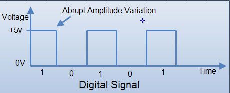
In digital circuit, a signal is represented in discrete states or logic levels. Digital signals are non-continuous and change in individual steps. They consist of pulses with discrete levels. The value of each pulse is constant but there is an abrupt change from one digit to next.

The signals in all present-day electronic digital systems have only two discrete values and are said to be binary. The digital-system design is restricted to use binary signals because of lower reliability of many valued electronic circuits. A circuit with ten states, using one discrete voltage value for each state, can be designed, but it would possess a very low reliability of operation. On the other hand, a circuit that has only two (ON or OFF) signal values can be constructed easily and is very reliable. Due to all these considerations, digital systems are constrained to take discrete values which are further constrained to take binary values.

Most digital circuits use two voltage levels labeled “Low” (0) and “High” (1). Often “Low” will be near 0 volts and “High” will be a higher depending on the supply voltage in use. The Below Fig. Shows a digital signal.

                         Most digital circuits use two voltage levels labeled

DIGITALTERMINOLOGY

Before going in further details of digital systems we shall first understand the basic terms and logics that are essential for the working of the digital electronics system.

(a) Logic Voltage Levels: Digital signals are represented by the two voltage levels which are referred to as logic voltage levels. A level logic is a logic in which the voltage levels represent logic 1 or logic O. There are two types of logics.

1. Positive Logic

2. Negative Logic

A positive logic system is the one in which higher of the two voltage levels rpresents the logic 1 and lower of the two voltage levels represents the logic O. A negative logic system is the one in which the lower of the two voltage levels represents the logic 1 and. the higher of the two voltage levels represent the logic O. So if two voltage levels are OV and +5V, then in the positive logic system, the OV represents a logic ‘0’ and the +5V represents a logic ‘1’. In negative logic system, it is the reverse, OV represents a logic’ l’ and +5V represents a logic ‘0’, (see in fig)

                       A positive logic system is the one in which higher of the two voltage levels represents the logic 1 and lower of the two voltage levels represents the logic O.

Unless or otherwise specified, all the signals are dealt with positive logic. Each logic gate is represented by a particular graphic symbol.

(b) Waveform: This refers to the shape and form of a signal such as a wave moving in a solid, liquid or gaseous medium. An instrument called oscilloscope can be used to pictorially represent the wave as a repeating image on a CRT or LCD screen. Some common periodic waveforms include sine waves, square wave etc. A digital waveform is generally in form of square wave.

(C) Digital Circuit: An electronic circuit that accepts and processes binary data according to the rules of Boolean logic (AND, OR NOT etc.) The simplest forms of digital circuits are built from logic gates, the building blocks of digital computer.

(d) Bit: Bit (‘Binary digit’) is a smallest unit of information storage and communication. It is the maximum amount of information that can be stored by a device or any other physical system that can normally exist in only two distinct states. These states are often interpreted as binary digits o and 1. They may also be interpreted as logical values, either true or false or two settings of a switch, either ‘on’ or ‘off’.

In modem computing devices, a bit is usually represented by an electrical voltage or current pulse, or by the electrical state of a flip-flop circuit. For devices using positive logic, a digit value of 1 is represented by a positive voltage relative to the electrical ground voltage (upto 5 volts in TTL designs), while a digit value of 0 is represented by 0 volts. In semiconductor memory, the two values of a bit may be represented by two levels of electrical charge stored in a capacitor.

(e) Nibble: It is equivalent to combination of four binary digits. For example: 1101, 1001, 1110 are all nibbles.

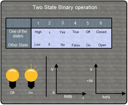
(I)Binary state terminology: The following table summarizes the binary state terminology.


The table summarizes the binary state terminology.

Analog System

By Dinesh Thakur

Most of the people are familiar with ordinary electrical circuits where voltages and currents can be measured with dial-type meters or analog meters as they are technically called. Such meters follow changes in voltage (or current) in a smooth step-less manner. This is what analog really means in electronics: signals or physical quantities which can vary in smooth-changing, a step-less manner. [Read more…] about Analog System

Primary Sidebar

Digital Electronics

Digital Electronics

  • Electronics - Codes
  • Electronics - Excess-3 Code
  • Electronics - BCD
  • Electronics - Binary Code Types
  • Electronics - Gray Code
  • Electronics - Digital System
  • Electronics - DSSS
  • Electronics - FHSS
  • Electronics - Analog System
  • Electronics - Diode
  • Electronics - Flip-flop
  • Electronics - Boolean Logic
  • Electronics - Analogue-to-digital
  • Electronics - Radio Modulations Types
  • Electronics - 8088
  • Electronics - ADC
  • Electronics - Breadboard
  • Electronics - 80486
  • Electronics - Amplitude Modulation
  • Electronics - Chip

Other Links

  • Digital Electronics - PDF Version

Footer

Basic Course

  • Computer Fundamental
  • Computer Networking
  • Operating System
  • Database System
  • Computer Graphics
  • Management System
  • Software Engineering
  • Digital Electronics
  • Electronic Commerce
  • Compiler Design
  • Troubleshooting

Programming

  • Java Programming
  • Structured Query (SQL)
  • C Programming
  • C++ Programming
  • Visual Basic
  • Data Structures
  • Struts 2
  • Java Servlet
  • C# Programming
  • Basic Terms
  • Interviews

World Wide Web

  • Internet
  • Java Script
  • HTML Language
  • Cascading Style Sheet
  • Java Server Pages
  • Wordpress
  • PHP
  • Python Tutorial
  • AngularJS
  • Troubleshooting

 About Us |  Contact Us |  FAQ

Dinesh Thakur is a Technology Columinist and founder of Computer Notes.

Copyright © 2025. All Rights Reserved.

APPLY FOR ONLINE JOB IN BIGGEST CRYPTO COMPANIES
APPLY NOW