There is no standard for representing data objects in ER diagrams. Each modeling methodology uses its own notation.
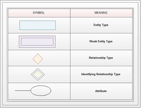
All notational styles represent entities as rectangular boxes and relationships as lines connecting boxes. Each style uses a special set of symbols to represent the cardinality of connection. The symbols used for the basic ER constructs are:
• Entities are represented by labeled rectangles. The label is the name of the entity. Entity names should be singular nouns.
• Attributes are represented by Ellipses.
• A solid line connecting two entities represents relationships. The name of the relationship is written above the line. Relationship names should be verbs and diamonds sign is used to represent relationship sets.
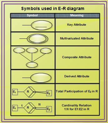
• Attributes, when included, are listed inside the entity rectangle. Attributes, which are identifiers, are underlined. Attribute names should be singular nouns.
• Multi-valued attributes are represented by double ellipses.
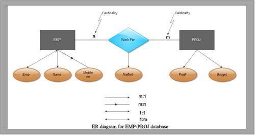
• Directed line is used to indicate one occurrence and un-directed line is used to indicate many occurrences in a relation.
The symbols used to design an ER diagram are shown.


The ER diagram showing the usage of different symbols

 Dinesh Thakur holds an B.C.A, MCDBA, MCSD certifications. Dinesh authors the hugely popular