In Entity-Relationship model a database is modeled as a collection of entities and relationship among entities. The ER model views the real world as a construct of entities and association between entities.
We’ll be covering the following topics in this tutorial:
Entities
An entity is an object whose information is stored in the database. It is distinguishable from other objects. For example: specific person, company, event, plant. In other words, any thing that may ‘have an independent existence and about which we intend to collect data is known as Entity. It is also known as Entity type.
Entities are the principal data object about which information is to be collected. Entities are usually recognizable concepts, either concrete or abstract, such as person, places, things, or events, which have relevance to the database. Some specific examples of entities are EMPLOYEES, PROJECTS, and INVOICES. An entity is analogous to a table in the relational model.
Entities are classified as independent or dependent (in some methodologies, the terms used are strong and weak, respectively). An independent entity is one that does not rely on another for identification. A dependent entity is one that relies on another for identification. An entity occurrence (also called an instance) is an individual occurrence of an entity. An occurrence is analogous to a row in the relational table.
Entity Set
An entity set is a set of entities of the same type that share the same properties. For example: set of all persons, companies, trees, holidays.
In object oriented terminology entity is considered as an object and entity set is considered as a class. For example, Student is an entity set or class and a particular student is an entity or an object.
Special Entity Types
Associative entities (also known as intersection entities) are entities used to associate two or more entities in order to reconcile a many-to-many relationship. Sub types entities are used in generalization hierarchies to represent a subset of instances of their parent entity, called the super type, but which have attributes or relationships that apply only to the subset. Associative entities and generalization hierarchies are discussed in more detail in next sections.
Relationships
A Relationship represents an association between two or more entities. Relationships are classified in terms of degree, connectivity, cardinality, and existence. An example of a relationship would be:
• Employees are assigned to projects
• Projects have sub-tasks
• Departments manage one or more projects
Attributes
Attributes describe the properties of the entity of which they are associated. A particular instance of an attribute is a value. For example, “Ram” is one value of the attribute Name.
The domain of an attribute is the collection of all possible values an attribute can have. The domain of Name is a character string.
Attribute
We can classify attributes as following types:
• Simple
• Composite
• Single-values
• Multi-values
• Derived
Simple Attribute: A simple attribute is an attribute composed of a single component with an independent existence. Simple attributes cannot be further subdivided. Examples of simple attributes include Sex, Age, and Salary etc. Simple attributes are sometimes called atomic attributes.
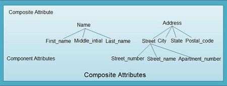
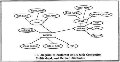
Composite Attribute: An attribute composed of multiple components, each with an independent existence is called a composite attribute. Some attributes can be further divided to yield smaller components with an independent existence of their own. For example, the Address attribute can be composed of components like Street number, Area, City, Pin code and so on. The decision to model the Address, Area, and City etc. is dependent on whether the user view of the model refers to the Address attribute as a single unit or as individual components. Composite attributes are shown.
Single-valued Attribute: A single-valued attribute is one that holds a single value for a single entity. The majority of attributes are single-valued for a particular entity. For example, the Classroom entity has as single value for the room_number attribute and therefore the room_number attribute is referred to as being single-valued.
Multi-valued Attribute: A multi-valued attribute is one that holds multiple values for a single entity. Some attribute has multiple values for a particular entity. For example, a student entity can have multiple values for the Hobby attribute-reading, music, movies and so on. A multi-valued attribute may have set of numbers with upper and lower limits. For example, the Hobby attribute of a Student may have between one and five values. In other words, a student may have a minimum of one hobby and maximum of 5 hobbies.
Derived Attribute: A derived attribute is one that represents a value that is derivable from the value of a related attribute or set of attributes, not necessarily in the same entity.
Some attributes may be related for a particular entity. For example the Age attribute can be derived from the date-of-birth attribute and therefore they are related. We refer the age attribute as a derived attribute, the value of which is derived from the date-of-birth attribute.
Degree of a Relationship
The degree of a relationship is the number of entities associated with the relationship. The n-ary relationship is the general form for degree n. Special cases are the binary, and ternary, where the degree is 2, and 3, respectively. Binary relationships, the association between two entities are the most common type in the real world. A recursive binary relationship occurs when an entity is related to itself. An example might be “some employees are married to other employees”. A ternary relationship involves three entities and is used when a binary relationship is inadequate. Many modeling approaches recognize only binary relationships. Ternary or n-ary relationships are decomposed into two or more binary relationships.
Connectivity and Cardinality
The connectivity of a relationship describes the mapping of associated entity instances in the relationship. The values of connectivity are “one” or “many”. The cardinality of a relationship is the actual number of related occurrences for each of the two entities.
The basic types of connectivity for relations are:
• One to One (1: 1).
• One to Many (1:M)
• Many to One (M:l)
• Many to Many (M:M)
A one-to-one (1:1) relationship is when at most one instance of an entity A is associated with one instance of entity B. For example, “employees in the company are each assigned their own office. For each employee there exists a unique office and for each office there exists a unique employee.
A one-to-many (1:M) relationships is when for one instance of entity A, there are zero, one, or many instances of entity B, but for one instance of entity B, there is only one instance of entity A. Examples of l:M relationships are:
• A department has many employees.
• Each employee is assigned to one department.
A many-to-one (M: 1) relationships is when for one instance of entity A is associated with at most one instances of entity B, but for one instance of entity B, there may be any number of instances of entity A. Examples of M: 1 relationships is
• Many employees one department.
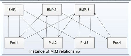
A many-to-many (M: M) relationship, sometimes called non-specific, is when for one instance of entity A, there are zero, one, or many instances of entity B and for one instance of entity B there are zero, one, or many instances of entity A. Examples are:
• Employees can be assigned to no more than two projects at the same time.
• Projects must have assigned at least three employees.
A single employee can be assigned to many projects; conversely, a single project can have assigned to it many employees. Here, the cardinality for the relationship between employees and projects is two and the cardinality between project and employee is three. Many-to-many relationships cannot be directly translated to relational tables but instead must be transformed into two or more one-to-many relationships using associative entities.
Direction
The direction of a relationship indicates the originating entity of a relationship. The entity from which a relationship originates is the parent entity; the entity where the relationship terminates is the child entity.
The type of the relation is determined by the direction of line connecting relationship component and the entity. To distinguish different types of relation, we draw either a directed line or an un-directed line between the relationship set and the entity set. Directed line is used to indicate one occurrence and un-directed line is used to indicate many occurrences in a relation as shown in next case.
To illustrate these different types of relationships consider the following entity sets:
DEPARTMENT, MANAGER, EMPLOYEE, PROJECT.
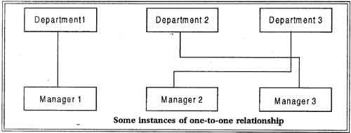
The relationship between a DEPARTMENT and a MANAGER is usually one-to-one; there is only one manager per department and a manager manages only one department. This relationship between entities is shown in figure 4.3. Each entity is represent by a rectangle and a direct line indicates the relationship between them. The relationship for MANAGER to DEPARTMENT and from DEPARTMENT to MANAGER is both 1:1. Note that a one to one relationship between two entity set does not imply that for an occurrence of an entity from one set at any time there must be an occurrence of an entity in the other set. In the case of an organization, there could be times when a department is without a manager or when an employee who is classified as a manager may be without a department to manage. Some instance of one to one relationship between the entities DEPARTMENT and MANAGER.

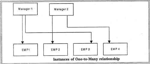
A one to many, relationship exists from the entity MANAGER to the entity EMPLOYEE because there are several employees reporting to the manager. As we just pointed out, there could be an occurrence of the entity type MANAGER having zero occurrences of the entity type EMPLOYEE reporting to him or her. A reverse relationship, from EMPLOYEE to MANAGER, would be many to one, since a single manager may supervise many employees However, given an instance of the entity set EMPLOYEE, there could be only one instance of the entity set MANAGER to whom that employee reports (assuming that no employee reports to more than one manager). The relationship between entities is illustrated and figure shows some instances of this relationship.

The relationship between the entity EMPLOYEE and the entity PROJECT can be derived as follows: Each employee could be involved in a number of different projects, and a number of employees could be working on a given project. This relationship Between EMPLOYEE and PROJECT is many to many. It is illustrated and shows some instances of such a relationship.

 Dinesh Thakur holds an B.C.A, MCDBA, MCSD certifications. Dinesh authors the hugely popular