When a company asks you to make them a working, functional Database Management System (DBMS) which they can work with, there are certain steps to follow. Let us summarize them here:
1. Gathering information: This could be a written document that describes the system in question with reasonable amount of details.
2. Producing ERD: ERD or Entity Relationship Diagram is a diagrammatic representation of the description we have gathered about the system.
3. Designing the database: Out of the ERD we have created, it is very easy to determine the tables, the attributes which the tables must contain and the relationship among these tables.
4. Normalization: This is a process of removing different kinds of impurities from the tables we have just created in the above step.
We’ll be covering the following topics in this tutorial:
How to Prepare an ERD
Step 1: Let us take a very simple example and we try to reach a fully organized database from it. Let us look at the following simple statement:
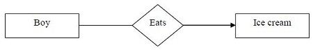
A boy eats an ice cream.
This is a description of a real word activity, and we may consider the above statement as a written document (very short, of course).
Step 2: Now we have to prepare the ERD. Before doing that we have to process the statement a little. We can see that the sentence contains a subject (boy), an object (ice cream) and a verb (eats) that defines the relationship between the subject and the object. Consider the nouns as entities (boy and ice cream) and the verb (eats) as a relationship. To plot them in the diagram, put the nouns within rectangles and the relationship within a diamond. Also, show the relationship with a directed arrow, starting from the subject entity (boy) towards the object entity (ice cream).
 Well, fine. Up to this point the ERD shows how boy and ice cream are related. Now, every boy must have a name, address, phone number etc. and every ice cream has a manufacturer, flavor, price etc. Without these the diagram is not complete. These items which we mentioned here are known as attributes, and they must be incorporated in the ERD as connected ovals.
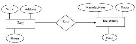 But can only entities have attributes? Certainly not. If we want then the relationship must have their attributes too. These attribute do not inform anything more either about the boy or the ice cream, but they provide additional information about the relationships between the boy and the ice cream.
Step 3: We are almost complete now. If you look carefully, we now have defined structures for at least three tables like the following:
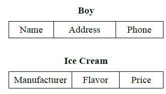
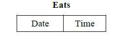 However, this is still not a working database, because by definition, database should be “collection of related tables.” To make them connected, the tables must have some common attributes. If we chose the attribute Name of the Boy table to play the role of the common attribute, then the revised structure of the above tables become something like the following.
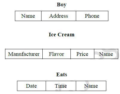
This is as complete as it can be. We now have information about the boy, about the ice cream he has eaten and about the date and time when the eating was done.
Cardinality of Relationship
While creating relationship between two entities, we may often need to face the cardinality problem. This simply means that how many entities of the first set are related to how many entities of the second set. Cardinality can be of the following three types.
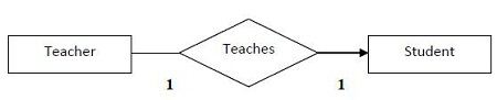
One-to-One
Only one entity of the first set is related to only one entity of the second set. E.g. A teacher teaches a student. Only one teacher is teaching only one student. This can be expressed in the following diagram as:
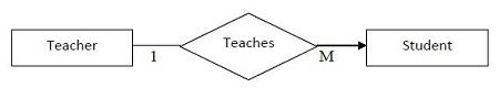
One-to-Many
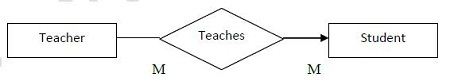
Only one entity of the first set is related to multiple entities of the second set. E.g. A teacher teaches students. Only one teacher is teaching many students. This can be expressed in the following diagram as:
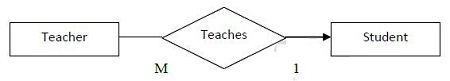
Many-to-One
Multiple entities of the first set are related to multiple entities of the second set. E.g. Teachers teach a student. Many teachers are teaching only one student. This can be expressed in the following diagram as:
Many-to-Many
Multiple entities of the first set is related to multiple entities of the second set. E.g. Teachers teach students. In any school or college many teachers are teaching many students. This can be considered as a two way one-to-many relationship. This can be expressed in the following diagram as:
In this discussion we have not included the attributes, but you can understand that they can be used without any problem if we want to.
The Concept of Keys
A key is an attribute of a table which helps to identify a row. There can be many different types of keys which are explained here.
Super Key or Candidate Key: It is such an attribute of a table that can uniquely identify a row in a table. Generally they contain unique values and can never contain NULL values. There can be more than one super key or candidate key in a table e.g. within a STUDENT table Roll and Mobile No. can both serve to uniquely identify a student.
Primary Key: It is one of the candidate keys that are chosen to be the identifying key for the entire table. E.g. although there are two candidate keys in the STUDENT table, the college would obviously use Roll as the primary key of the table.
Alternate Key: This is the candidate key which is not chosen as the primary key of the table. They are named so because although not the primary key, they can still identify a row.
Composite Key: Sometimes one key is not enough to uniquely identify a row. E.g. in a single class Roll is enough to find a student, but in the entire school, merely searching by the Roll is not enough, because there could be 10 classes in the school and each one of them may contain a certain roll no 5. To uniquely identify the student we have to say something like “class VII, roll no 5”. So, a combination of two or more attributes is combined to create a unique combination of values, such as Class + Roll.
Foreign Key: Sometimes we may have to work with an attribute that does not have a primary key of its own. To identify its rows, we have to use the primary attribute of a related table. Such a copy of another related table’s primary key is called foreign key.
Strong and Weak Entity
Based on the concept of foreign key, there may arise a situation when we have to relate an entity having a primary key of its own and an entity not having a primary key of its own. In such a case, the entity having its own primary key is called a strong entity and the entity not having its own primary key is called a weak entity. Whenever we need to relate a strong and a weak entity together, the ERD would change just a little.
Say, for example, we have a statement “A Student lives in a Home.” STUDENT is obviously a strong entity having a primary key Roll. But HOME may not have a unique primary key, as its only attribute Address may be shared by many homes (what if it is a housing estate?). HOME is a weak entity in this case.
The ERD of this statement would be like the following
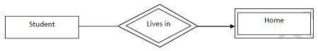
As you can see, the weak entity itself and the relationship linking a strong and weak entity must have double border.
Different Types of Database
There are three different types of data base. The difference lies in the organization of the database and the storage structure of the data. We shall briefly mention them here.
Relational DBMS
This is our subject of study. A DBMS is relational if the data is organized into relations, that is, tables. In RDBMS, all data are stored in the well-known row-column format.
Hierarchical DBMS
In HDBMS, data is organized in a tree like manner. There is a parent-child relationship among data items and the data model is very suitable for representing one-to-many relationship. To access the data items, some kind of tree-traversal techniques are used, such as pre-order traversal.
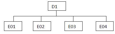
Because HDBMS is built on the one-to-many model, we have to face a little bit of difficulty to organize a hierarchical database into row column format. For example, consider the following hierarchical database that shows four employees (E01, E02, E03, and E04) belonging to the same department D1.
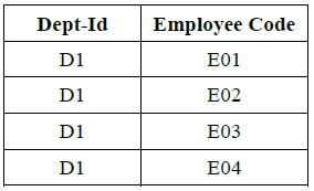
There are two ways to represent the above one-to-many information into a relation that is built in one-to-one relationship. The first is called Replication, where the department id is replicated a number of times in the table like the following.
Replication makes the same data item redundant and is an inefficient way to store data. A better way is to use a technique called the Virtual Record. While using this, the repeating data item is not used in the table. It is kept at a separate place. The table, instead of containing the repeating information, contains a pointer to that place where the data item is stored.
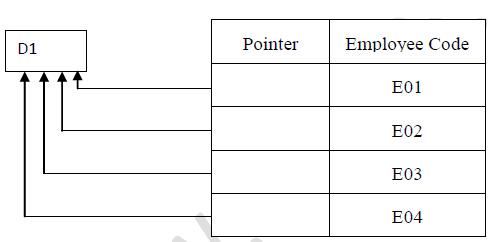
This organization saves a lot of space as data is not made redundant.
Network DBMS
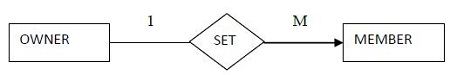
The NDBMS is built primarily on a one–to-many relationship, but where a parent-child representation among the data items cannot be ensured. This may happen in any real world situation where any entity can be linked to any entity. The NDBMS was proposed by a group of theorists known as the Database Task Group (DBTG). What they said looks like this:
In NDBMS, all entities are called Records and all relationships are called Sets. The record from where the relationship starts is called the Owner Record and where it ends is called Member Record. The relationship or set is strictly one-to-many.
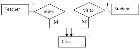
In case we need to represent a many-to-many relationship, an interesting thing happens. In NDBMS, Owner and Member can only have one-to-many relationship. We have to introduce a third common record with which both the Owner and Member can have one-to-many relationship. Using this common record, the Owner and Member can be linked by a many-to-many relationship.
Suppose we have to represent the statement Teachers teach students. We have to introduce a third record, suppose CLASS to which both teacher and the student can have a many-to-many relationship. Using the class in the middle, teacher and student can be linked to a virtual many-to many relationship.
 Dinesh Thakur holds an B.C.A, MCDBA, MCSD certifications. Dinesh authors the hugely popular