SONET (Synchronous Optical Network) is a physical level standard, proposal by Bellcore (Bell Communications Research) in the mid-80s for transmission through an optical fiber. SONET is a technique of transport between two nodes, which defines the interface adopted for the NNI (Network Node Interface). Standardized by the ANSI and recommended worldwide by the CCITT, SONET can be thought of as a physical network for a global communication system in the same way that a twisted pair LAN can see as the communication system of a corporate network. It is a potentially global network, built on fiber optic cable, with standardized data transmission speeds and recognized worldwide. SONET eliminates limits between telephone companies worldwide.
SONET defines the transmission of synchronous and asynchronous information (time-sensitive data such as real-time video). With SONET, telecommunications companies can provide their customers with fast networks that are initially metropolitan scale (MAN) and that at some point can become global in scope, since SONET makes possible the connection of the equipment of telecommunications companies worldwide. The transmission rates of digital signals have been different according to the countries, which has prevented the development of global transmission systems. For example, DS-1 defines 1,544 Mbps in the United States, while E1, its European counterpart, defines 2,048 Mbps. SONET defines its unique digital hierarchy with OC (optical carrier) levels.
SONET defines the fiber-optic network for the transport of the signals, and the different wide area network (WAN) technologies, such as the Multimegabit Data Switching Service (SMDS) and the Asynchronous Transfer Mode (ATM), work on here. These technologies are cell transmission, not frames (frames) of variable length; therefore, they are easily adaptable to the possible transmission speeds in SONET networks.
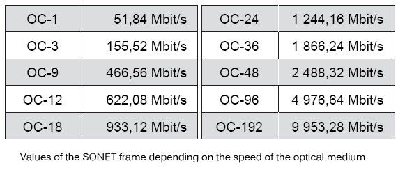
SONET describes the composition of a synchronous frame transmitted every 125 microseconds. The length of this field depends on the speed of the interface. Its various values are listed in table depending on the speed of the optical medium, or OC (Optical Carrier).

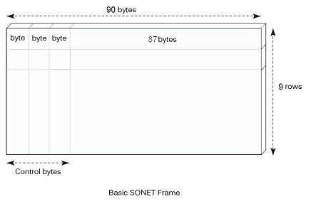
As illustrated in the figure, the SONET frame comprises in the first three bytes of each row of synchronization and supervisory information. Cells are transmitted in the frame. The start time of the sending of a cell is not necessarily the beginning of the frame, but can be located anywhere in the frame. Supervision bits preceding the beginning so that one does not waste time for the emission of a cell. 
When the signals arrive in the transport SONET module, they are not copied directly as such but in a virtual container (Virtual Container). This filling is called adaptation. SONET and SDH include several types of virtual containers, called VC-N (Virtual Container level N). In these containers, it is necessary to add management information located in the byte start of each row. By adding this additional information, we define an administrative unit, or AU-N (Administrative Unit-N).
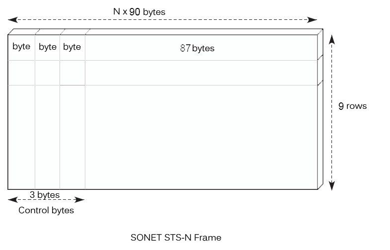
The higher levels still have nine rows, but there is n times 90 bytes per row for the level N. The N-level frame of the SONET hierarchy is illustrated in figure.

The SONET standard is used for the implementation of the physical layer of the ATM cell switched networks and the interconnection of the operator networks. The flow rates used for the ATM access interfaces are respectively 155 Mbit/s, 622 Mbit/s and 2.488Gbit/s for OC3, OC12 and OC48’s.
A very important feature of SONET is more reliable communication in the event of breakage or failure of one of its components. SONET found in metropolises have a loop topology. Two paths are thus available to go from one point to another, in particular of the user at the operator’s core network. SONET allows changing this path in 50 ms. During a break in communication in one direction of the loop, the reconfiguration can be done in a time resulting in a barely detectable break for two people talking to each other. This ability of reconfiguration is a key strength of SONET / SDH structures.
We’ll be covering the following topics in this tutorial:
SONET layers
The current SONET standards contain the specifications for the “fibre-to-fibre” interfaces at the physical (photonic) level. These determine the speed of the optical line, wavelength, energy levels, pulse shapes, and coding. The standards also define, in a complete way, the structure of the frame, the headers, and the mapping of the payload.
The physical layer of SONET / SDH subdivided into four sub-layers:
• The lower sublayer is called the photonic sublayer and specifies the physical characteristics of the light and fibre used, which can be single mode or multimode and always work in the second window.
• The section sublayer deals with point-to-point links between any contiguous elements (repeaters, multiplexers or switches).
• the line sublayer is responsible for multiplexing and demultiplexing tributaries between two multiplexers.
• the route sublayer deals with problems related to end-to-end communication.
As we can see, there is a certain parallel between the four sub-layers of SONET / SDH and the first four layers of the OSI model.
Sonet network elements
A SONET / SDH system consists of a set of switches, multiplexers and repeaters, all interconnected by optical fibre. If, for example, you want to interconnect two computers using an STM-1, you physically connect to two SDH multiplexers (also called ADM, Add-Drop Multiplexer), which in turn interconnected by two fibres (one for each direction). Depending on the distance between the ADMs, the use of repeaters may be necessary. Several ring-shaped multiplexers can be connected, in which case the data always travels in the same direction, so that full-duplex communication is achieved using a single fibre to constitute the ring; however, it is reasonable to use two fibres and have one of them in case of failure, with automatic switching in a matter of milliseconds. You can also make more complex, meshed topologies, using SDH switches.
The fibre that directly joins any two SDH devices (multiplexers, switches or repeaters) called a section; the union between two adjacent multiplexers (possibly through repeaters) is known as a line; Finally, the definition of a complete communication path between two multiplexers for the interconnection of two final equipment (which can cross several repeaters and intermediate multiplexers) is called a route.
Although the network elements (NEs, Network Elements) are compatible at the OC-n level, they may differ in some characteristics between one vendor and another. SONET does not restrict manufacturers to provide a single type of product, nor does it require them to provide all types.
For example, one vendor could offer an add/drop multiplexer with DS-1 access only, while another could offer simultaneous access to DS-1 and DS-3.
Current SONET transport networks employ different topologies to meet the objectives of network simplicity, cost containment, bandwidth efficiency and maintenance over time. For example, an optical hub configuration can be used to eliminate the need for expensive and complicated configuration with back-to-back network elements. Similarly, a self-repairing ring network can be developed to ensure continuous service through geographically dispersed and redundant roads.
 Dinesh Thakur holds an B.C.A, MCDBA, MCSD certifications. Dinesh authors the hugely popular