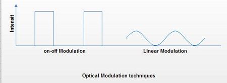
Like other communication system, fiber optic communication has also a transmitter at one end of the system, which injects information on to the fiber cables. The transmitter processes and translates coded electronic pulse information coming from copper wire into equivalently coded light pulses. The basic concept behind the optical transmitter is that it converts electrical input signals into modulated light for transmission over an optical fiber. The input signal determines the characteristics of the resulting modulated light, which may be turned on and off or may be linearly varied in intensity between two predetermined levels.

There are two commonly· used optical sources for generating the light pulses. These are light emitting diode (LED) and Laser Diode (LD). Laser diode with its version as injection-laser diode (ILD) is commonly employed. Both the sources funnel the light pulses into the fiber-optic medium where they transmit themselves down the fiber cable and are placed in very close proximity to the light emitting region to couple as much light as possible into the fiber. To accomplish the same, they are mounted in a package that enables an optical fiber to couple as .much light as possible into the fiber.
Light Emitting Diode (LED) – Diodes are electronic semiconductor components that allow current Pass in only one direction. Similarly, light emitting diodes are semiconductor devices that emit visible light when an electric current passes through it in a forward direction. When several LEDs are placed side-by-side, they can create pictures. In most of the LEDs, light may be considered monochromatic having single wavelength. These wavelengths may range from 700 nanometers to 400 nanometers (red to blue-violet). Some LEDs also emit infrared IR (830 nanometers or longer). These are known as an Infrared Emitting Diode (IRED). Light from a Light Emitting Diode (LED) is created in much the same way that light is created in a fluorescent tube or neon sign. In an LED crystal the electrons of its atoms are pumped up to higher energy states, and when they fall back down again, each atom gives off a particle/wave of light. However, the electrons in an LED are not exactly the same as the gas molecules in a neon sign.
It consists of P-type semiconductor and N-type semiconductor. These two elements are placed in direct contact, forming a region called the P-N junction which usually resembles a semiconductor diode but differs in the size and shape of P-N junction area in addition to transparent package so that visible or IR light may pass through. When LEDs are compared with incandescent and fluorescent illuminating devices, its benefits may be looked into low power requirement, high efficiency, long life etc. The applications include indicator lights, LCD panel back lighting, fiber optic data transmission, remote control, optoisolators etc.
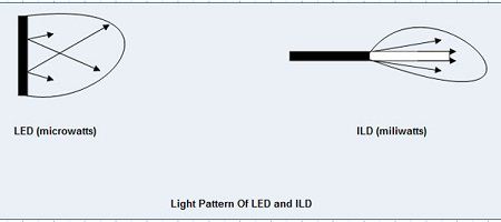
 LEDs have relatively large emitting areas and as a result are not as good light sources as ILDs. However, they are widely used for short to moderate transmission distances because they are much more economical, quite linear in terms of light output’ versus electrical current input and stable in terms of light output versus ambient operating temperature and concentrate light into a tighter cone pattern.
Injection Laser diode (lLD) It is also known as a laser diode. Like LEDs, these are also semiconductor devices that produce coherent radiation in the visible or IR spectrum when current passes through it. Laser diodes find extensive use in fiber optic communication systems, compact disc (CD) players, laser printers, remote-control devices etc. There are other conventional lasers based upon helium-neon (He-Nel, ruby, and gas types. Laser diodes have several advantages over conventional lasers – they are smaller in size and less in weight, have low power requirements, low intensity, wide-angle beam etc. Unlike LEDs, ILDs have very small light emitting surfaces and can couple many times more power to the fiber than LEDs. The characteristics of ILDs may be seen into linear response. of light output versus electrical current input. They are not stable over wide operating temperature ranges and require more elaborate circuitry to achieve acceptable stability and are therefore costly. These are useful for situations that require the transmission of signals ·over long distances.
 The amount of light emitted by LED or ILD is required to be coupled with the fiber in the optical fiber system. The optical light, which is getting into optical fiber, is a function of a number of factors. These are the intensity of the optical source, the area of the light-emitting surface, the acceptance angle of the fiber, and the losses due to reflections and scattering.
- Intensity The design of the optical source plays a major role in deciding the intensity and is usually specified in terms of total power output at a particular drive current.
- Area The amount of light emitted and injected into fiber depends on the light emitting surface compared to the area of the light accepting core of the fiber and it is inversely proportional the area.
- Acceptance Angle The aperture of fiber will also decide how much energy can be allowed to enter into the fiber. The injection of light at the aperture of the core at a particular angle will certainly playa crucial role because the transmission of light through the fiber cable follows the principle of total internal reflection. If the acceptance angle is more than a specified angle the light getting incident upon fiber may not pass through it. Therefore, the acceptance angle of a fiber, which is expressed in terms of numeric aperture (NA), must lie between a specified range of angles. Typical values for numerical Aperture (NA) are 0.1-0.4, which correspond to acceptance angles of 11°-46°. The numerical aperture (NA) is defined as the sine of one half of the acceptance angle of the fiber.
- Other Losses Losses may be counted in fiber from opaque obstructions on the surface of a fiber, reflection from the entrance and exit surface of any fiber. The loss due to entrance and exit surface is called the Fresnell Loss and is equal to about 4% for each transition between air and glass. Using special coupling gels between glass surfaces may reduce these losses. Losses also occur when the light travels through the actual fiber. These losses drop on increasing the wavelength that is they are inversely proportional to wavelength. Some typical range of these losses 4-6 dB per km and 3-4 dB per km at a wavelength of 850 nanometers and 1300 nanometers, respectively. These losses are primarily the result of random scattering of light and absorption by actual impurities within the glass. The excessive bending of fiber also causes some of the light to leave the core area of the fiber. The smaller the bend radius, the greater the loss.
 Dinesh Thakur holds an B.C.A, MCDBA, MCSD certifications. Dinesh authors the hugely popular