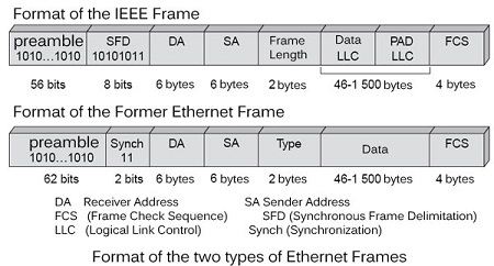
The Ethernet frame is designed to transport packets in enterprise networks by an original method for broadcasting on a local network. This solution gave birth shared Ethernet, in which the broadcast frame is transmitted and where only the station that recognizes the right to copy the information. To this solution dissemination has added Ethernet switching.
Before turning on the various types of Ethernet switches, Ethernet indicate uses a frame well as the Ethernet block is preceded by a series of 8 bytes starting with 1010101010101010101, and so on until the end of eighth byte, which ends with 11. This preamble is long enough to ensure it is not possible to find the same succession between two preambles, the probability of finding this sequence being 1/264.
The structure of the Ethernet frame has been standardized by the IEEE (Institute of Electrical and Electronics Engineers), having been originally defined by the triumvirate of industrial Xerox, Digital and Intel. Two Ethernet frames coexist so primitive version of the triumvirate and the founder of standardization by the IEEE. The format of these two frames is shown in Figure.

In the case of the IEEE frame, the preamble is followed by a start message box, called SFD (Start Frame Delimiter), whose value is 10101011. In ancient frame, it is followed by 2 synchronization bits. Both sequences are in fact identical, and only the presentation differs from one frame to another.
The frame contains the address of the sender and receiver, each of 6 bytes. These addresses with a specific form of the Ethernet world, designed such there are no two couplers in the world who have the same address. In this addressing, said plate, the first three bytes correspond to a manufacturer number, and the next three to a serial number. In the first three bytes, the two bits Initial have special meaning. Set to 1, the first bit indicates group address. If the second bit is also set to 1, it indicates that the address does not follow the standard structure.
Let’s look at first following the IEEE frame. The Length field (Length) indicates the length of the data field from the upper layer. the frame then encapsulates the frame level block itself, or LLC frame (Logical Link Control). This encapsulated frame contains a PAD area, which allows to fill the field data so as to reach the value of 46 bytes, which is the minimum length that must reach this zone so that the total frame make 64 bytes including the areas of Preamble and delimitation.
The former Ethernet frame further includes a type, which indicates how this data area (Data). For example, if the value of this area is 0800 in hexadecimal, this means that the Ethernet frame carries an IP packet.
Error detection is provided by means of a generator polynomial g (x) of formula:
g(x) = x32 + x26 + x22 + x16 + x12 + x11 + x10 + x8 + x7 + x5 + x4 + x2 + x1
This polynomial gives birth to a control sequence (CRC) of 4 bytes. To connect to the Ethernet network, a machine uses a coupler, that is to say a card that is inserted into the machine and supports the software and network equipment necessary for the connection.
As we have seen, the Ethernet frame contains a preamble. This allows the receiver to synchronize its clock and its various physical circuits with the issuer, to correctly receive the frame. In the case of a shared Ethernet network, all network couplers record the frame as and when its path. The electronic component responsible for extracting data included in the frame checks the match between the address of the destination station in the frame and scope the address of the coupler. If there is a match, the packet is transferred to the user after checking the compliance of the frame through the control sequence.
 Dinesh Thakur holds an B.C.A, MCDBA, MCSD certifications. Dinesh authors the hugely popular