• Skip to main content
  • Skip to primary sidebar
  • Skip to secondary sidebar
  • Skip to footer

Computer Notes

Library
    • Computer Fundamental
    • Computer Memory
    • DBMS Tutorial
    • Operating System
    • Computer Networking
    • C Programming
    • C++ Programming
    • Java Programming
    • C# Programming
    • SQL Tutorial
    • Management Tutorial
    • Computer Graphics
    • Compiler Design
    • Style Sheet
    • JavaScript Tutorial
    • Html Tutorial
    • Wordpress Tutorial
    • Python Tutorial
    • PHP Tutorial
    • JSP Tutorial
    • AngularJS Tutorial
    • Data Structures
    • E Commerce Tutorial
    • Visual Basic
    • Structs2 Tutorial
    • Digital Electronics
    • Internet Terms
    • Servlet Tutorial
    • Software Engineering
    • Interviews Questions
    • Basic Terms
    • Troubleshooting
Menu

Header Right

Home » Networking » Communication » Optical Connectors
Next →
← Prev

Optical Connectors

By Dinesh Thakur

This is very simple optical fiber communication system. In this particular scenario, the optical fiber requires one connection to the transmitter side and another connection at the receiver side. In another scenario when it is required to communicate over long distances where more than one length of fiber cable and other supporting equipment are placed in the system.

The optical fiber in each case needs to be connected to the peripheral equipment and themselves to communicate using optical connectors. These connectors are similar to their electrical counterparts in function and outward appearance but are actually high precision devices. These connectors are placed axially with light gathering core of optical fiber and therefore lie directly over and in line with the light source or other fiber. Being the core size of 50 microns and fiber size of 0.002 inch, the optical connectors require a high precision and tolerance.
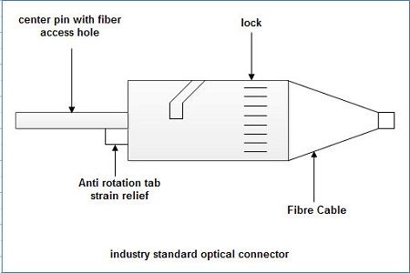
Optical Connector

There are many different types of optical connectors in use today which includes SMA connector, ST connector used for single-mode, multi-mode fibers or both. Sometimes, two optical connectors are matched together using a device referred to by different names such as uniter, adopter, or coupler.

We’ll be covering the following topics in this tutorial:

  • Optical Splices
  • Optical Receivers
  • PIN Diode

Optical Splices

Other than the optical connectors there are other methods also which result in much lower losses in splicing two optical fiber cables together. The two most common methods are fusion splicing and mechanical splicing. They produce splice losses in the range of 0.15 dB-OJ dB.
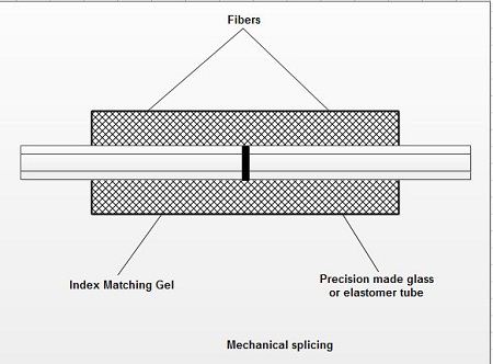
Mechanical SplicingThe ends of two pieces of fiber are cleaned and stripped. A mechanical assembly helps in butting and aligning these ends carefully together by friction or compression. A special type gel is used at the point of contact to reduce light reflection and keep the splice loss at a minimum.
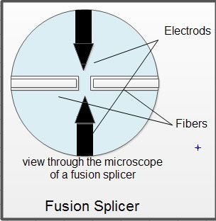
Fusion Splicer

The two ends are actually put on melting to get them fused together, which provides a continuous fiber without a break. It is accomplished with the help of special expensive splicing equipment, which can be performed very quickly. It appears to be costlier affair but if it is done in large volume the cost is substantially reduced. As fusion splices are fragile, mechanical devices are usually employed to protect them.

Optical Receivers

As soon as the light pulses reach their destination they need to be reconstructed into the original signal and therefore, they are channeled into the optical receiver through optical detector. As its name implies it detects the received light incident on it and to convert it to an electrical signal containing the information impressed on the light at the transmitting end. The electronic information is then ready for input into electronic based communication devices, such as a computer telephone, or TV. These detectors are light sensitive elements, which are encased, in a special adapter similar to the one used for the LED or LD. A photosensitive device like photo diode .of either the PIN or the avalanche type are usually used in which optical light coming out from the optical cable strikes an exposed section of a P-N junction of semiconductor material. These detectors work on a principle when a photon strikes a semiconductor, it can allow a movement of electron and thus creating an electron and hole pair. The concentration of these electron hole pairs is dependent on the amount of light striking the semiconductor, making the semiconductor suitable as an optical detector. The P-N junction -usually has a large sensitive detecting area that can be several hundred microns in diameter. The major advantage of having large exposed area makes the alignment of fiber and the receiving device much less critical than it is in optical transmitters. Besides, optical receivers are equipped with high gain internal amplifiers to take care of quite small light that exits a fiber.

Therefore, we may now define that a typical fiber optic receiver consists of an optical detector, a low noise amplifier, and other circuitry used to produce the output electrical signal.

Typical Design of a Optical Receiver

PIN Diode

A PIN photo-diode is a semiconductor P-N junction which operates on reverse biased voltage that is the flow of current is maintained in a direction opposite to the conduction of the diode. In this case, the diode acts as an open switch. When there is no light incident on the diode, a current is always there which is known as dark current.

Avalanche Photo-diodes

An Avalanche Photo-diode (APD) is a photo-diode that internally amplifies the current by an avalanche process in which a very high voltage in the order of volts is applied in the reverse direction of the conduction of the diode. This voltage initially accelerates the electron generated by the incident photons and subsequently they force other electrons in the semiconductor material to join them because of heavy collision. This process is known as avalanche multiplication. Avalanche multiplication continues to occur until the electrons move out of the active area of the APD.

The factors affecting the characteristics of these diodes are listed below:

  1. Dynamic range Dynamic range is the parameter which decides the range of optical power levels over which the receiver operates within the specified values as in case of digital transmission and analog transmission SNR are defined. It usually is described by the ratio of the maximum input power to the sensitivity.
  2. Response Time Response time depends upon factors such as the thickness of the detector active area and the detector RC time constant. The thickness of P-N junction decides the total time taken by electron to travel the junction. This time is referred to as the electron transit time. The thicker the P-N junction area, .the longer the transit time will be. The product of RC represents time constant. The value of RC must be small for a better response. The capacitance of the photo detector must be kept small to prevent the RC time constant from limiting the response time. The photo-diode capacitance consists mainly of the junction capacitance and any capacitance relating to packaging.
  3. Linearity They are highly linear devices and therefore, produce the output electrical current in proportion to input light.

You’ll also like:

  1. Optical Fiber – Optical Transmission Modes Advantages and Disadvantages of Optical Fiber
  2. Optical Source
  3. Passive Optical Network
  4. Ethernet Passive Optical Network (EPON)
  5. What is Fiber Optics (Optical Fiber)? – Definition
Next →
← Prev
Like/Subscribe us for latest updates     

About Dinesh Thakur
Dinesh ThakurDinesh Thakur holds an B.C.A, MCDBA, MCSD certifications. Dinesh authors the hugely popular Computer Notes blog. Where he writes how-to guides around Computer fundamental , computer software, Computer programming, and web apps.

Dinesh Thakur is a Freelance Writer who helps different clients from all over the globe. Dinesh has written over 500+ blogs, 30+ eBooks, and 10000+ Posts for all types of clients.


For any type of query or something that you think is missing, please feel free to Contact us.


Primary Sidebar

Networking

Networking Tutorials

  • Network - Home
  • Network - Uses
  • Network - Advantages
  • Network - Classification
  • Network - Architecture Type
  • Nework - Networks Vs Comms

Networking Devices

  • Network - Modem
  • Network - Routers Types
  • Network - Bluetooth
  • Network - RS-232C
  • Network - Hub
  • Network - Devices
  • Network - Bridges
  • Network - Repeaters
  • Network - Routers
  • Network - Switching Hubs
  • Network - Transceiver
  • Network - Multiplexer
  • Network - Gateway
  • Network - BNC Connector
  • Network - Optical Connectors
  • Network - NICs
  • Networking Protocol

  • Protocol - Definition
  • Protocol - IP
  • Protocol - Aloha
  • Protocol - MAC Layer
  • Protocol - Sliding Window
  • Protocol - Stop & Wait
  • Protocol - Network Protocols
  • Protocol - Token Passing
  • Protocol - SIP
  • Protocol - Ad-Hoc Networks Routing
  • Protocol - Lap-f
  • Protocol - Point-to-Point
  • Protocol - PPP
  • Protocol - PPP Phases
  • Protocol - LDP
  • Protocol - MPLS
  • Protocol - MPOA
  • Protocol - HDLC
  • Protocol - Distance Vector routing
  • Protocol - IGMP
  • Protocol - ICMP
  • Protocol - SLIP
  • Protocol - DVMRP
  • Protocol - SDLC
  • Protocol - Routing
  • Protocol - UDP
  • Protocol - ARP and RARP
  • Protocol - Link-State
  • Protocol - ARP Table
  • Protocol - RTP
  • Protocol - NHRP
  • Network Addressing

  • Addressing - Home
  • Addressing - SubNetting
  • Addressing - Classless
  • Addressing - Classes or Classful
  • Addressing - IPV4 vs IPV6
  • Addressing - IPv6
  • Addressing - Subnet Mask
  • Addressing - MAC Address
  • Addressing - Supernetting
  • Addressing - Private IP
  • Addressing - IPv4
  • Addressing - Public IP
  • Addressing - Multihomed
  • Addressing - Indirect Addressing
  • Addressing - ASP
  • Addressing - VLSM
  • Addressing - Routing Algorithms
  • Addressing - Hierarchical Routing
  • Addressing - Routing
  • Addressing - Distributed Routing
  • Addressing - Data Routing
  • Addressing - Services
  • Addressing - IP forwarding
  • Addressing - Aging
  • Addressing - Algorithm CR
  • Networking Media

  • Transmission - Home
  • Transmission - Modes
  • Transmission - Media
  • Transmission - System
  • Transmission - Bound
  • Transmission - Unbound
  • Transmission - Baseband
  • Transmission - Wired
  • Transmission - Fiber Benfits
  • Transmission - Infrared
  • Transmission - UnGuided
  • Transmission - Microwave
  • Transmission - Infrared
  • Transmission - Radio Wave
  • Transmission - Network
  • Transmission - Digital Signal
  • Transmission - Data
  • Transmission - Asynchronous
  • Transmission - Sync Vs Async
  • Cable - Twisted-Pair
  • Cable - Coaxial
  • Cable - UTP and STP
  • Cable - Fiber Optics
  • Cable - Gigabit Ethernet
  • Cable - Fast Ethernet
  • Cable - Ethernet Cable
  • Cable - Fiber-Optic Using
  • Cable - CATV
  • Cable - 100Base T
  • Cable - 10BASE T
  • Cable - 10 Base 2
  • Cable - 10 Base 5
  • Networking Types

  • IEEE - 802.11
  • IEEE - 802.5
  • IEEE - 802.15
  • IEEE - 802.11e
  • IEEE - 802.11n
  • Network - Ethernet
  • Network - Arpanet
  • Network - Frame Relay
  • Network - X.25
  • Network - Telephone
  • Network - WSN
  • Network - Metro Ethernet
  • Network - WAN Ethernet
  • Network - Wireless Mesh
  • Network - SAN
  • Network - SNA
  • Network - Cisco Architecture
  • Network - Vlan
  • Network - FDDI
  • Network - 100VG-Any
  • Network - EPON
  • Network - ISDN
  • Network - ARCNet
  • Network - Passive Optical
  • Networking Reference Models

  • Models - TCP/IP
  • Models - OSI
  • Models - MAC Layer
  • Models - Network Layer
  • Models - MAC Layer Functions
  • Models - TCP/IP Vs OSI
  • Models - CSMA
  • Models - CSMA/CD
  • Models - CSMA/CA
  • Models - CDMA
  • Models - STDM
  • Models - FDMA
  • Models - TDMA
  • Models - SDH
  • Models - CDM
  • Models - Multiplexing
  • Models - Reference
  • Models - Random Access Methods
  • Models - TCP/IP Architecture
  • Models - FDM
  • Models - IP Header
  • Models - OTN
  • Models - Amplitude Levels
  • Models - MIMO
  • Models - Plesiochronous Media
  • Models - Half Duplex
  • Models - ISO Architecture
  • Models - Data-Link Layer
  • Models - WDM
  • Models - Duplex
  • Models - Ethernet FDSE
  • Networking Switching Techniques

  • Switching - Home
  • Switching - Techniques
  • Switching - Packet
  • Switching - Circuit
  • Switching - Message
  • Switching - Packet Vs virtual Circuit
  • Switching - Cell
  • Switching - ATM Cell Structure
  • Switching - Virtual Circuit Vs Datagram
  • Switching - Time Space
  • Switching - Modulation
  • Switching - Cell Relay
  • Switching - ATM Structure
  • Switching - VC Vs PVC
  • Switching - Packet and Circuit
  • Switching - VPC
  • Switching - IP
  • Switching - Logical Channels
  • Switching - TDM
  • Switching - FDM
  • Network Codes

  • Codes - CRC
  • Codes - Error Correction and Detection
  • Codes - Hamming
  • Codes - Piggybacking
  • Codes - Encoding Techniques
  • Codes - Error Control
  • Codes - Parity Check
  • Codes - Parity bit
  • Codes - Bit Error
  • Codes - CRC
  • Codes - Transmission Errors
  • Codes - Error Detection and Correction
  • Network Communication

  • Communication - Home
  • Communication - Satellite
  • Communication - Wireless
  • Communication - Data Type
  • Communication - Congestion Control
  • Communication - Network
  • Communication - Data
  • Communication - Software
  • Communication - Layering Process
  • Networking Signaling

  • Signal - Analog
  • Signal - Digital
  • Signal - Analog Vs Digital
  • Signal - Digitization
  • Network Security

  • Security - Home
  • Security - Requirements
  • Security - Threats
  • Security - Services

Other Links

  • Networking - PDF Version

Footer

Networking Tutorials

  • Network - Home
  • Network - Uses
  • Network - Advantages
  • Network - Classification
  • Network - Architecture Type
  • Nework - Networks Vs Comms

Networking Devices

  • Network - Modem
  • Network - Routers Types
  • Network - Bluetooth
  • Network - RS-232C
  • Network - Hub
  • Network - Devices
  • Network - Bridges
  • Network - Repeaters
  • Network - Routers
  • Network - Switching Hubs
  • Network - Transceiver
  • Network - Multiplexer
  • Network - Gateway
  • Network - BNC Connector
  • Network - Optical Connectors
  • Network - NICs
  • Networking Protocol

  • Protocol - Definition
  • Protocol - IP
  • Protocol - Aloha
  • Protocol - MAC Layer
  • Protocol - Sliding Window
  • Protocol - Stop & Wait
  • Protocol - Network Protocols
  • Protocol - Token Passing
  • Protocol - SIP
  • Protocol - Ad-Hoc Networks Routing
  • Protocol - Lap-f
  • Protocol - Point-to-Point
  • Protocol - PPP
  • Protocol - PPP Phases
  • Protocol - LDP
  • Protocol - MPLS
  • Protocol - MPOA
  • Protocol - HDLC
  • Protocol - Distance Vector routing
  • Protocol - IGMP
  • Protocol - ICMP
  • Protocol - SLIP
  • Protocol - DVMRP
  • Protocol - SDLC
  • Protocol - Routing
  • Protocol - UDP
  • Protocol - ARP and RARP
  • Protocol - Link-State
  • Protocol - ARP Table
  • Protocol - RTP
  • Protocol - NHRP
  • Network Addressing

  • Addressing - Home
  • Addressing - SubNetting
  • Addressing - Classless
  • Addressing - Classes or Classful
  • Addressing - IPV4 vs IPV6
  • Addressing - IPv6
  • Addressing - Subnet Mask
  • Addressing - MAC Address
  • Addressing - Supernetting
  • Addressing - Private IP
  • Addressing - IPv4
  • Addressing - Public IP
  • Addressing - Multihomed
  • Addressing - Indirect Addressing
  • Addressing - ASP
  • Addressing - VLSM
  • Addressing - Routing Algorithms
  • Addressing - Hierarchical Routing
  • Addressing - Routing
  • Addressing - Distributed Routing
  • Addressing - Data Routing
  • Addressing - Services
  • Addressing - IP forwarding
  • Addressing - Aging
  • Addressing - Algorithm CR
  • Networking Media

  • Transmission - Home
  • Transmission - Modes
  • Transmission - Media
  • Transmission - System
  • Transmission - Bound
  • Transmission - Unbound
  • Transmission - Baseband
  • Transmission - Wired
  • Transmission - Fiber Benfits
  • Transmission - Infrared
  • Transmission - UnGuided
  • Transmission - Microwave
  • Transmission - Infrared
  • Transmission - Radio Wave
  • Transmission - Network
  • Transmission - Digital Signal
  • Transmission - Data
  • Transmission - Asynchronous
  • Transmission - Sync Vs Async
  • Cable - Twisted-Pair
  • Cable - Coaxial
  • Cable - UTP and STP
  • Cable - Fiber Optics
  • Cable - Gigabit Ethernet
  • Cable - Fast Ethernet
  • Cable - Ethernet Cable
  • Cable - Fiber-Optic Using
  • Cable - CATV
  • Cable - 100Base T
  • Cable - 10BASE T
  • Cable - 10 Base 2
  • Cable - 10 Base 5
  • Networking Types

  • IEEE - 802.11
  • IEEE - 802.5
  • IEEE - 802.15
  • IEEE - 802.11e
  • IEEE - 802.11n
  • Network - Ethernet
  • Network - Arpanet
  • Network - Frame Relay
  • Network - X.25
  • Network - Telephone
  • Network - WSN
  • Network - Metro Ethernet
  • Network - WAN Ethernet
  • Network - Wireless Mesh
  • Network - SAN
  • Network - SNA
  • Network - Cisco Architecture
  • Network - Vlan
  • Network - FDDI
  • Network - 100VG-Any
  • Network - EPON
  • Network - ISDN
  • Network - ARCNet
  • Network - Passive Optical
  • Networking Reference Models

  • Models - TCP/IP
  • Models - OSI
  • Models - MAC Layer
  • Models - Network Layer
  • Models - MAC Layer Functions
  • Models - TCP/IP Vs OSI
  • Models - CSMA
  • Models - CSMA/CD
  • Models - CSMA/CA
  • Models - CDMA
  • Models - STDM
  • Models - FDMA
  • Models - TDMA
  • Models - SDH
  • Models - CDM
  • Models - Multiplexing
  • Models - Reference
  • Models - Random Access Methods
  • Models - TCP/IP Architecture
  • Models - FDM
  • Models - IP Header
  • Models - OTN
  • Models - Amplitude Levels
  • Models - MIMO
  • Models - Plesiochronous Media
  • Models - Half Duplex
  • Models - ISO Architecture
  • Models - Data-Link Layer
  • Models - WDM
  • Models - Duplex
  • Models - Ethernet FDSE
  • Networking Switching Techniques

  • Switching - Home
  • Switching - Techniques
  • Switching - Packet
  • Switching - Circuit
  • Switching - Message
  • Switching - Packet Vs virtual Circuit
  • Switching - Cell
  • Switching - ATM Cell Structure
  • Switching - Virtual Circuit Vs Datagram
  • Switching - Time Space
  • Switching - Modulation
  • Switching - Cell Relay
  • Switching - ATM Structure
  • Switching - VC Vs PVC
  • Switching - Packet and Circuit
  • Switching - VPC
  • Switching - IP
  • Switching - Logical Channels
  • Switching - TDM
  • Switching - FDM
  • Network Codes

  • Codes - CRC
  • Codes - Error Correction and Detection
  • Codes - Hamming
  • Codes - Piggybacking
  • Codes - Encoding Techniques
  • Codes - Error Control
  • Codes - Parity Check
  • Codes - Parity bit
  • Codes - Bit Error
  • Codes - CRC
  • Codes - Transmission Errors
  • Codes - Error Detection and Correction
  • Network Communication

  • Communication - Home
  • Communication - Satellite
  • Communication - Wireless
  • Communication - Data Type
  • Communication - Congestion Control
  • Communication - Network
  • Communication - Data
  • Communication - Software
  • Communication - Layering Process
  • Networking Signaling

  • Signal - Analog
  • Signal - Digital
  • Signal - Analog Vs Digital
  • Signal - Digitization
  • Network Security

  • Security - Home
  • Security - Requirements
  • Security - Threats
  • Security - Services

Other Links

  • Networking - PDF Version

Programming

  • Java Programming
  • Structured Query (SQL)
  • C Programming
  • C++ Programming
  • Visual Basic
  • Data Structures
  • Struts 2
  • Java Servlet
  • C# Programming
  • Basic Terms
  • Interviews

World Wide Web

  • Internet
  • Java Script
  • HTML Language
  • Cascading Style Sheet
  • Java Server Pages
  • Wordpress
  • PHP
  • Python Tutorial
  • AngularJS
  • Troubleshooting

 About Us |  Contact Us |  FAQ

Dinesh Thakur is a Technology Columinist and founder of Computer Notes.

Copyright © 2025. All Rights Reserved.

APPLY FOR ONLINE JOB IN BIGGEST CRYPTO COMPANIES
APPLY NOW