Multiplexing or (muxing) – To combine multiple signals (analog or digital) for transmission over a single line or media. A common type of multiplexing combines several low-speed signals for transmission over a single high-speed connection. In other words, we can say that Muxing used for sharing of a medium and its link by two or more devices. It can provide both Efficiency and Privacy.
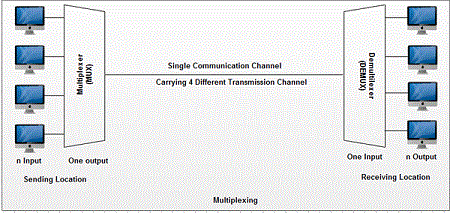
Multiplexing is done by using a device called multiplexer (MUX) that combines n input lines to generate one output line i.e. (many to one). Therefore multiplexer (MUX) has several inputs and one output.
At the receiving end, a device called demultiplexer (DEMUX) or (demuxing) is used that separates signal into its component signals. So DEMUX has one input and several outputs.
We’ll be covering the following topics in this tutorial:
Concept of Multiplexing
As shown in figure multiplexer takes 4 input lines and diverts them to a single output line. The signal from 4 different devices is combined and carried by this single line. At the receiving side, a demultiplexer takes this signal from a single line and breaks it into the original signals and passes them to the 4 different receivers.

Advantages of Multiplexing
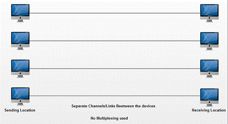
If no multiplexing is used between the users at two different sites that are distance apart, then separate communication lines would be required as shown in fig.
This is not only costly but also become difficult to manage. If multiplexing is used then, only one line is required. This leads to the reduction in the line cost and also it would be easier to keep track of one line than several lines. Multiplexing efficient for utilization of bandwidth.

The word path refers to the physical link. The word channel refers to a portion of the path that carries a transmission between a specific pair of devices. A road can have many (n) channels.
The signals are multiplexed using three basic techniques: frequency division multiplexing (FDM), time-division multiplexing (TDM) and wave division multiplexing (WDM). TDM further subdivided into synchronous RDM (usually referred to as TDM only) and asynchronous TDM, also called static TDM or concentrator.
The following are several examples of different multiplexing methods:
Frequency division multiplexing (FDM)
It is used in the analogue signal, a multiplexing technique that uses different frequencies to combine multiple streams of data for transmission over a communications medium. FDM assigns a different carrier frequency to each data stream and then combines many modulated carrier frequencies for transmission. The carrier frequencies are separated by a sufficient bandwidth to accommodate the modulated signal. These ranges of bandwidth are the channels through which the different signals travel.
For example, television transmitters use FDM to broadcast several channels at once. The bandpass filter is used for separating channels and allows to pass a specific range of frequencies. During transmission of streams, it blocks lower and higher frequencies. In Frequency Division Multiplexing, channels are separated by unused strips of guard bands to prevent Overlapping. Guard bands increase the bandwidth for FDM.
The figure shows a conceptual view of FDM. In this illustration, the transmission path divided into three parts, each representing a channel that carries a transmission. As an analogy, imagine a point where three narrow streets meet to form a three-lane highway. Each of these streets corresponds to a lane of the highway. Each car entering the highway from one of the streets still has its lane and can travel without interfering with the cars on the other lanes.
Remember that although Figure shows the path as if it had a spatial division into separate channels, actual channel divisions are achieved by frequency, not by spatial separation.
The figure is a conceptual illustration in the time domain of the multiplexing process. The FDM is an analog process and is shown in the figure using phones as input devices.
Time Division Multiplexing (TDM)
A type of multiplexing that combines data streams by assigning each stream a different time slot in a set. TDM is designed for digital signals, which combining several low-rate channels into high-rate one. TDM repeatedly transmits a fixed sequence of time slots over a single transmission channel. Within T-Carrier systems, such as T-1 and T-3, TDM combines Pulse Code Modulated (PCM) streams created for each conversation or data stream. TDM, slots are further divided into Frames. In order to separate channels AND gates are used in a TDM receiver.
The Figure gives a conceptual view of the TDM. Note that the same link used as in FDM; However, here the link is shown sectioned by time instead of frequency.
In Fig. TDM the portions of signals 1,2,3 and 4 occupy a link sequentially. As an analogy, imagine a chairlift that has several streets. Each street has its line, and the skiers of each line take turn occupying the ski lift. As each chair reaches the top of the mountain, the skier who goes on, it gets off and skiing under the mountain where he waits again in the queue.
TDM can be implemented in two ways: synchronous TDM and asynchronous TDM. Synchronous means that the multiplexer always assigns the same time slot to each device, whether or not the device has something to transmit. For example, time slot A is assigned only to device A and cannot use for any other device. Each time the assigned time is up, the device has the opportunity to send a portion of its data. If the device is unable to transmit or has no data to send, its time slot remains empty.
Synchronous TDM does not guarantee that the full capacity of the link can use. It is more likely that only a portion of the time slots can be used at a given time. Because the time slots are pre-assigned and fixed, each time a connected device is not transmitting its corresponding time slot is empty, and that link capacity wasted. For example, imagine that the output of 20 identical computers on a line has been multiplexed. Using synchronous TDM, the line speed must be at least 20 times the speed of each input line. However, what happens if there are only 10 computers they use at the same time. Half the capacity of the line is wasted. Asynchronous multiplexing is designed to avoid this type of expense. As with the term synchronous, the term asynchronous means something different in multiplexing than it means in other areas of data communication. Here it means flexible or not fixed.
Like synchronous TDM, asynchronous TDM allows you to multiplex a certain number of low-speed input lines over a single high-speed line. However, unlike synchronous TDM, in asynchronous TDM, the total speed of the input lines may be greater than the capacity of the track. In a synchronous system, if we have n input lines, the frame contains a fixed m number of at least n time slots. In an asynchronous system, if there are n input lines, the frame does not contain more than n slots, with m less than n (see Figure). In this way, the asynchronous TDM supports the same number of input lines as the synchronous TDM with a smaller link capacity. Alternatively, given the same link, asynchronous TDM can support more devices than synchronous TDM.
The number of time slots in an asynchronous TDM frame (m) based on a statistical analysis of the number of input lines that are likely to transmit at a given time. Instead of being pre-assigned, each slot is available for any input device connected to the lines that have data to send. The multiplexer looks at the input lines, accepts portions of data until a frame is full and then sends the frame through the link. If there is not enough data to fill all the slots in a frame, the frame is transmitted partially filled; that is, the total link capacity may not use one hundred percent of the time. However, the ability to dynamically allocate time slots, associated with the lower ratio of time slots to input lines, dramatically reduces the probability and the degree of expense.
Wave Division Multiplexing (WDM)
It used in the analog signal, a type of multiplexing developed for use on optical fibre. The idea is the same: different signals on different frequencies are combined. However, the difference is that the frequencies are very high. WDM is the optical equivalent of FDM.
The figure gives a conceptual view of a WSM multiplexer and demultiplexer. Very narrow bands of light from different sources combine to achieve a wider band of light. In the receiver, the signals separated by the demultiplexer.
One can ask what the mechanism of the WDM is. Although technology is very sophisticated, the idea is straightforward. You want to combine multiple beams of light within a single light in the multiplexer and do the reverse operation in the demultiplexer. Combining and dividing beams of light are quickly resolved through a prism. Remember from fundamental physics that a prism curves a beam and light based on the angle of incidence and frequency. Using this technique, a demultiplexer can make that combines different beams of input light, each of which contains a narrow frequency band, into a single output beam with a broader frequency band. It can also be done in a demultiplexer to do the operation to reverse the process. The figure shows the concept.
 Dinesh Thakur holds an B.C.A, MCDBA, MCSD certifications. Dinesh authors the hugely popular