RS-232C is a long-established standard (“C” is the current version) that describes the physical interface and protocol for relatively low-speed serial data communication Networks between computers and related devices.
RS-232C is the interface that your computer uses to talk to and exchange data with your modem and other serial devices. RS-232C is the interface between your Communication networks and other communication networks.
Somewhere in your PC, typically on a Universal Asynchronous Receiver/Transmitter (UART) chip on your motherboard, the data from your computer is transmitted to an internal or external modem (or other serial device) from its Data Terminal Equipment (DTE) interface. Since data in your computer flows along parallel circuits and serial devices can handle only one bit at a time, the UART chip converts the groups of bits in parallel to a serial stream of bits.
As your PC’s DTE agent, it also communicates with the modem or other serial device, which, in accordance with the RS-232C standard, has a complementary interface called the Data Communications Equipment (DCE) interface. RTS/CTS is the way the DTE indicates that it is ready to transmit data and the way the DCW indicates that it is ready to accept data
RS232C, a standard interface approved by the Electronic Industries Alliance (EIA) for connecting serial devices. In 1987, the EIA released a new version of the standard and changed the name to EIA-232-D. And in 1991, the EIA teamed up with Telecommunications Industry association (TIA) and issued a new version of the standard called EIA/TIA-232-E. Many people, however, still refer to the standard as RS-232C, or just RS-232.
Almost all modems conform to the EIA-232 standard and most personal computers have an EIA-232 port for connecting a modem or other device. In addition to modems, many display screens, mice, and serial printers are designed to connect to a EIA-232 port. In EIA-232 parlance, the device that connects to the interface is called a Data Communications Equipment (DCE) and the device to which it connects (e.g., the computer) is called a Data Terminal Equipment (DTE).
The EIA-232 standard supports two types of connectors — a 25-pin D-type connector (DB-25) and a 9-pin D-type connector (DB-9). The type of serial communications used by PCs requires only 9 pins so either type of connector will work equally well.
Although EIA-232 is still the most common standard for serial communication, the EIA has recently defined successors to EIA-232 called RS-422 and RS-423. The new standards are backward compatible so that RS-232 devices can connect to an RS-422 port.
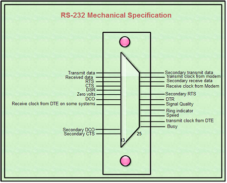
RS-232 Mechanical Specification
There is a standardized pin out for RS-232 on a DB25 connector, as shown in Figure.

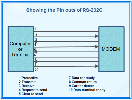
The essential feature ofRS-232 is that the signals are carried as single voltages referred to a common ground on pin 7. In its simplest form, the RS-232:C interface consis;9’of only two wires for data and ground. The ground is the absolute voltage reference for all the interface circuitry, the point in the circuit from which all voltages are measured. Data on pin 2 of the DTE is transmitted, while the same data on pin 2 of a DCE (modem) is received data as shown in Figure.
Data is transmitted and received on pins 2 and 3, respectively. Data Set Ready (DSR) is an indication from the Data set (the modem or DSU/CSU) that it is on. Similarly, DTR indicates that the DTE is on. Carrier Detect (CD) indicates that carrier for the transmission data is on.
Pins 4 and 5 carry the Request to Send (RTS) and Clear to Send (CTS) signals. In most situations, RTS and CTS are constantly on the communication session. However, where the DTE is connected to a multi-point line, RTS is used to turn the carrier on the modem on and off. On a multi-point line, it is imperative that only one station is transmitting at a time. When a station wants to transmit, it raises RTS. The modem turns on carrier, typically waits a few milliseconds for carrier to stabilize, and raises CTS.
The DTE transmits when it sees CTS up. When the station has finished its transmission, it drops RTS and the modem drops CTS and carrier together.

Terminals and modems usually communicate bidirectionally. Bidirectional interchange between the two devices is directly analogous to the connection of two telephones. The differences between the DTE and DCE are that DTEs transmit on pin 2 and receive on pin 3. DCEs transmit on pin 3 and receive on pin 2. When the modem is communicating with another modem, three essential links are established. These are:
1. DTE to DCE The DTE or terminal and modem or DCE talk to each other.
2. DCE to DCE The two modems on the link talk to each other. When a DCE to DCE connection is established the modem will send a connect message to the computer. The connect message specifies the computer about the baud rate being used by the two modems for communication.
In case of modems with dissimilar baud rate, the modem of higher baud rate is set to send the data at the same rate of the other modem using the computer’s communication program.
3. DTE to DCE The host computer talks with its modem.
The output signal level usually swings between +12v and,-12v. RS-232 is simple, universal, well understood and supported everywhere. However, it has some serious shortcomings as an electrical interface.
First, the interface presupposes a common ground between the DTE and DCE. This is a reasonable assumption where a short cable connects a DTE and DCE in the same room, but with longer lines and connections between devices that may be on different electrical buses, this may not be true. Second, a signal on a single line is impossible to screen effectively for noise. By screening the entire cable one can reduce the influence of outside noise, but internally generated noise remains a problem. As the baud rate and line length increase, the effect of capacitance between the cables introduces serious cross talk until a point is reached where the data itself is unreadable. Low capacitance cable can reduce cross-talk. Also, as it is the higher frequencies that are the problem control of slew rate in the signal (i.e. making the signal more rounded, rather than square) also decreases the cross-talk. The original specifications for RS-232 had no specification for maximum slew rate.
The standards for RS-232 and similar interfaces usually restrict RS-232 to 20 kbps or less and line lengths of 15m (50 ft) or less. These restrictions are mostly throwbacks to the days when 20 kbps were considered a very high line speed, and cables were thick, with high capacitance, However, in practice, RS-232 is fur more robust than the traditional specified limits of 20 kbps over u 15m line would imply. Most 56 kbps DSUs are supplied with both V.35und RS-232 ports because RS-232 is perfectly adequate at speeds up to 200 kbps. The 15 m limitation for cable length can be stretched to about 30 m for ordinary cable, if well screened and grounded, and about 100 m if the cable is Jaw capacitance as well.
 Dinesh Thakur holds an B.C.A, MCDBA, MCSD certifications. Dinesh authors the hugely popular