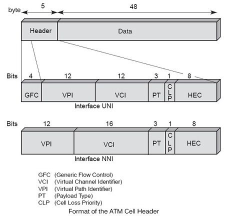
As explained above, the cell is formed of exactly 53 bytes, comprising 5 bytes of header and 48 bytes of data.
The data area contains a fragment of a user packet, generally a fragment of an IP packet. Of the 48 bytes from the upper layer, up to 4 bytes can relate supervision, that is to say, the packet fragmentation is carried out in 44-byte block. The 4 bytes of supervision are detailed somewhat further, in the section devoted to the upper layer or AAL (ATM adaption layer).

The 5-byte ATM frame’s supervision forming the header is shown in Figure.

The header
In the header, the bit GFC (Generic Flow Control) is used for access control and flow control at the terminal portion, between the user and the network. When multiple users want to enter the ATM network through a single point of entry, it must order their requests. This control is simultaneously an access technique, such as LANs, and a flow control on what goes into the network. Unfortunately for the ATM world, this area has never been standardized, which is a strong handicap for user interfaces. In the absence of standard terminal interfaces, it was not possible to compete with ATM IP interface, which eventually prevailed in all terminal machines.
In the control field, 3 bits PT (Payload Type) define the type of information transported into the cell, including the management and control of the network. The eight options for this field are:
• 000: User data cell, no congestion; indication of an ATM network the user level to another user of the ATM network = 0;
• 001: User data cell, no congestion; indication of an ATM network the user level to another user of the ATM network = 1;
• 010: User data cell, congestion; indicating a level of the user ATM network to another user of the ATM network = 0;
• 011: User data cell, congestion; indicating a level of the user ATM network to another user of the ATM network = 1;
• 100: management unit for the OAM F5 segment;
• 101: management unit for the OAM F5 end to end;
• 110: cell for resource management;
• 111: reserved for future functions.
Then comes the CLP (Cell Loss Priority), which indicates whether the cell can be lost (CLP = 1) or, conversely, if it is large (CLP = 0). This bit’s function assist in flow control. Before transmitting a cell in the network, it should be respect a Fed rate negotiated at the time of the opening of the virtual circuit. He is always possible to enter cells redundant, but we must provide them with a indicator to identify compared to baseline. The operator of ATM network can lose data redundant to enable information inputs as part of the control flow to pass smoothly.
The last part of the control area, the HEC (Header Error Control), is for the protection of the header. This field allows to detect and correct an error in standard mode. When an error in the header is detected and a correction is not possible, the cell is destroyed. We return to this point a little further to describe the procedure and demonstrate the use of this field to edit the timing when it is lost.
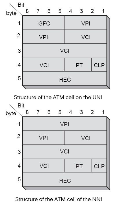
As explained two interfaces were defined in ATM: the input UNI and the network output and the NNI between two nodes within the network. The ATM cell structure is not exactly the same on both interfaces. The ATM cell structure on the UNI is illustrated in Figure on one and the NNI in Figure.
The GFC field is used to control the flow of cells entering the network, the multiplexing and reduce congestion periods of the end user network, called CPN (Customer Premise Network). GFC provides the performance required by the user, as the bandwidth allocated or negotiated traffic rates. The ITU-T has defined in recommendation I.361 two sets of procedures for GFC, transmission procedures controlled and uncontrolled ones. For non-controlled transmission procedures, 0000 is placed in the GFC field. In this case, the GFC has no role.

In summary, the two main functions performed by the GFC are:
• The short-term flow control;
• The control of the quality of service within the end user system.
The GFC field only exists on the UNI. The four bits of the GFC field are replaced within the network on the NNI interfaces by four other bits, which are expanding the reference. When a user positions the four GFC bits on its interface, these four bits are cleared in the network to be replaced by additional reference number and therefore never reach the recipient. In other words, these four bits can be used for transmission of information from end to end but only locally on the input interface in the network.
 Dinesh Thakur holds an B.C.A, MCDBA, MCSD certifications. Dinesh authors the hugely popular