Fast Ethernet is based on twisted pair and fiber-optic media systems, and provide high-speed network channels for use in the backbone systems. Fast Ethernet standard uses a particular protocol called auto-negotiation protocol that allows multi-speed Ethernet interfaces to be built. This section deals with 100BaseT.
To speed up the original Ethernet system to 100 Mbps, keeping the original CSMA/CD medium access control mechanism as it is. This approach is called 100Base-T Fast Ethernet. 100BaseT is the IEEE specification for the 100Mbps Ethernet implementation over Unshielded Twisted-Pair (UTP) and Shielded Twisted-Pair (STP) cabling.
We’ll be covering the following topics in this tutorial:
100BaseT
100BaseT is a high-speed LAN standard and is considered a variation of 10BaseT. 100BaseT uses the existing IEEE 802.3 CSMA/ CD specification. As a result, 100BaseT retains the IEEE 802.3 frame format, size, and error-detection mechanism. Also, it supports all applications and networking software currently running on 802.3 networks. 100BaseT supports dual speeds of 10 and 100Mbps using 100BaseT Fast Link Pulses (FLPs). 100BaseT hubs must detect dual speeds much like Token H.ing4/16 hubs, but adapter cards can support 10 Mbps, 100 Mbps, or both. Compared to the 10 Mbps specifications, the 100 Mbps systems have a ten-fold reduction of bit-time, which is the amount of time it takes to transmit a bit on the Ethernet channel. It produces a tenfold increase in the speed of the packets over the media system. However, the other important aspects of the Ethernet system such as the frame format, the amount of data a frame may carry, and the media access control mechanism, are all unchanged. Fast Ethernet provides a mechanism called Auto-negotiation to set the speed of transfer. It makes it possible for vendors to provide dual-speed Ethernet interfaces that can be installed and run at either 10Mbps or 100Mbps automatically.
100BaseT Physical Media
There are three types of fast Ethernet media for transmitting 100Mbps Ethernet signals. They are:
100BaseT4
100BaseTX
100BaseFX
Each media type name consists of three parts. The first part, “100”, stands for the media speed of 100 Mbps. The “Base” stands for “base-band”, which is a type of signaling. Base-band signaling simply means that Ethernet signals are the only signals carried over the media system. The third part provides an indication of the segment type. The “T4” segment type is a twisted-pair segment that uses four pairs of telephone-grade twisted-pair wire. The “TX” segment type is a twisted-pair segment that uses two pairs of wires and is based on twisted-pair physical medium standard developed by ANSI. The “FX” segment type is a fiber optic link segment, based on the fiber optic physical medium standard developed by ANSI, and that uses two strands of fiber cable. The TX and FX medium standards are collectively known as 100BaseX.The 100BaseTXand 100BaseFXmedia standards used in Fast Ethernet are both adopted from physical media standards first developed by ANSI, the American National Standards Institute. The ANSI physical media standards were originally developed for the Fiber Distributed Data Interface (FODI) LAN standard (ANSI standard X3T9.5), and are widely used in FDDI LANs. The T4 standard was provided to make it possible to use lower-quality twisted-pair wire for 100 Mbps Ethernet signals.
Type of 100Base T
The 100BaseT can be divided into 100BaseTX, 100BaseT4 and 100BaseFX, depending on the type of transmission media used as explained above. Two pair category 5 UTP, four pair category 3 UTP and optical fiber cable are used for 100BaseTX, 100BaseT4 and 100BaseFX, respectively. This standard has been defined in IEEE802.3u.

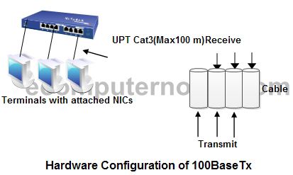
The hardware configuration of 100BaseTx. As with 100Baset, terminals are connected to the hub with 100BaseTx. CatS UTPs are used for connection. 100BaseTx has been developed based on 10BaseT to enable a higher transmission speed, vendors can readily develop peripheral equipment for 100BaseTx. Virtually, all hubs and NICs for 100BaseTxcan also be used for 10BaseT.
The hardware configuration of 100BaseT4. It is same as that for 100BaseTx. Cat3 UTPs are used for connection. Although originally intended for use as transmission lines at 10Mbps, cables of this type now offer a transmission speed of 100 Mbps as a result of special arrangements, including improved signal processing and simultaneous use of three out of four pairs for transmission or reception. This enables the trouble free introduction of a 100 Mbps LAN without the need to replace 10BaseT cables. However, these cables must be four pair cables.
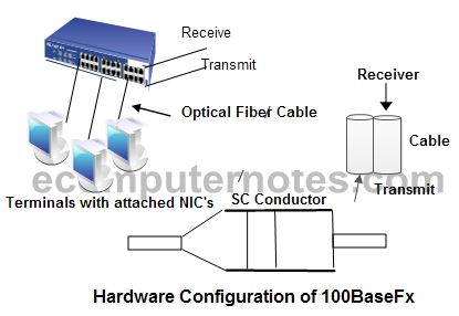
The hardware configuration of 100BaseFx. The SC connector that is a push-lock type is recommended for use as an interface connector. However, some other connectors including the ST connector are also defined as options. Two fiber cables one for transmission and the other for reception are required for each connection.
The 100BaseT Interconnection Mechanism
The main components of the 100BaseT network are the physical medium, the Media Independent Interface (MII), Media Dependent Interface (MDI) and Physical Layer Device (PHY). The MII is used with a 100Mbps external transceiver to connect a 100Mbps Ethernet device to any of the three media types. The MII has a 40-pin plug and cable that stretches up to 0.5 meters. The MDI is a mechanical and electrical interface between the transmission medium and the physical-layer device. The PHY provides either 10 or 100 Mbps operation and can be a set of integrated circuits on an Ethernet port, or an external device supplied with an MII cable that plugs into an MII port on a 100BaseT device. PHY performs the functions of a transceiver.
Figure illustrates typical station connection. The DTE (computer) contains an Ethernet interface, which forms and sends Ethernet frames that carry data between computers attached to the network. The Ethernet interface is attached to the physical media, using a set of equipments that might include a media independent cable and a physical layer interface (transceiver), with its associated MDI (twisted-pair RJ45-style jack or fiber optic connector). The interface or repeater port might also be designed to include the PHY electronics internally in which case, the design of MDI depends on the type of physical medium used. Each media type in the Fast Ethernet system has a separate PHY and MDI, specifically designed and wired for use on that kind of segment.
100BaseT Operation
100BaseT and 10 Base T use the same IEEE 802.3MAC access and collision-detection methods, and they also have the same frame format and length requirements. The main difference between 100BaseTand 10BaseT (other than the obvious speed differential) is the network diameter. The 100BaseT maximum network diameter is 205 meters which is approximately 10times less than 10Mbps Ethernet. Reducing the 100BaseT network diameter is necessary because 100BaseT uses the same collision-detection mechanism as 10BaseT. With 10BaseT, distance limitations are defined so that a station knows while transmitting the smallest legal frame size (64 bytes) that a collision has taken place with another sending station that is located at the farthest point of the domain. To achieve the increased throughput of 100BaseT, the size of the collision domain has to shrink. This is because the propagation speed of the medium has not changed, so a station transmitting 10 times faster must have a maximum distance that is 10 times less.
100baseT Auto negotiation Option
100BaseT networks support an optional feature, called auto negotiation. This feature enables a device and a hub to exchange information (using 100BaseT FLPs) about their capabilities, thereby creating an optimal communications environment. Auto negotiation supports a number of capabilities. Some of them are:
- Speed matching for devices that support both 10-and 100-Mbps operations.
- Full-duplex mode of operation for devices that support the above said communications speeds.
- Provides an automatic signaling configuration for 100BaseT4 and 100BaseTX stations.
Figure describes the characteristics of 100BaseT system.
100BaseTX Segments
100BaseTX is based on the American National Standards Institutes (ANSI) Twisted-pair-Physical Medium Dependent (TP-PMD) specification. The ANSI TP-PMD supports Unshielded Twisted-pair and Shielded Twisted-pair cabling. The components used to build a 100Base-TX twisted-pair segment are the network medium, 100BaseTX Repeaters, 100BaseTX Crossover Wiring, and 100Base-TX Link Integrity Test.
The 100Base-TX Ethernet segments are defined as link segments in the Ethernet specifications. A link segment is formally defined as a point-to-point medium that connects two and only two MDIs. The smallest network built with a link segment would consist of two computers, one at each end of the link segment. A more typical installation uses multipart repeater hubs, or packet-switching hubs, to provide a connection between a larger numbers of link segments. The Ethernet interface is connected to the computer at one end of the link segment, and the other end of the link segment is connected to the hub. In this way, many link segments with their associated computers can be connected to hub ports and all computers communicate via the hub.
The 100BaseTX specifications allow a segment of up to 100 meters. Two 100 meter 100BaseTX segments can be connected together through a single repeater. This provides a system with a total diameter of 200 meters between nodes. The physical topology supported by twisted-pair link segments is the star. In this topology, a set of link segments are connected to a hub, radiating out from the hub to the computers like the rays from a star.
100BaseFX Segments
The set of components required to build a 100BaseFX fiber optic segment are the transmission medium, MDI Connectors, and 100BaseFX repeaters. Note that while a single 100BaseFX segment may be up to 412 meters in length, when no repeaters are used, the maximum distance between computers will be less. There are two types of repeaters used for connecting 100BaseFX segments. They are class I and class II repeater. If a single class II repeater is used to link fiber segments, then the maximum distance between any two nodes linked with all fiber segments may be 320 meters. This maximum distance is also called the maximum collision domain diameter. If a single Class I repeater is used, then the maximum distance between DTEs linked with all fiber segments may be 272 meters. Finally, if two Class II repeaters are used, the maximum distance between two DTEs linked with all fiber segments may be 228 meters. The physical topology supported by fiber optic link segments is the star.
 Dinesh Thakur holds an B.C.A, MCDBA, MCSD certifications. Dinesh authors the hugely popular