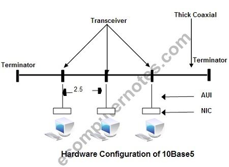
This uses traditional thick baseband coaxial cable in bus topology to connect multiple computers as shown. This single transmission line is called a segment. A coaxial cable 10 mm in diameter, known as a thick coaxial cable is used as a transmission line. A terminator is connected at each end of the cable. Note that proper data communication cannot be assured even if one of these terminators is missing or not properly connected.
A transceiver is used to connect a coaxial cable and terminals. A transceiver cable (also referred to as an AUI (Attachment Unit Interface) cable) is used to connect a transceiver and the NIC. The maximum length of this cable is 50 meters. Up to 100 transceivers can be connected to each segment. A 10 Mbps cable is like a yellow hose. The maximum length of the cable is 2.5 meters with direction markings. The direction markings help to find out where the cable goes.
The following are the characteristics of the thick Ethernet (10base5)
• Cable supports to a maximum of 500 meters.
• It provides connectivity to a maximum of 1024 stations.
• Maximum distance covered by a network using thick Ethernet is 2.5 km.
• Maximum number of stations supported by the Ethernet is 1024.
A medium-sized network based on Ethernet is shown in Figure
All stations are connected to a coaxial cable. A group of stations connected to a cable forms a segment. A device called repeater is used to link two network segments, which are separated by long distance. Each station is connected to the Ethernet cable through a transceiver. A transceiver is a transmitter-receiver pair, which can extract or insert signals on a cable in one direction. A repeater consists of two transceivers. Hence, it is able to transmit and receive both directions. 
10Base stands for 10Mbps and baseband transmission system. The 5 of 10Base5 Signify a maximum of 500 meter segment length. The segment may be extended up to 1500 meters by using repeaters.
Implementation of Ethernet: General Implementation of an Ethernet is shown in Figure. The two significant layers that are implemented are the physical layer and the data link layer.
The physical layer performs the following functions:
(a) Encoding the data: This process generates the synchronization bits called preamble for the data frame at the transmitter. At the receiver, it removes the preamble from the received frame. The physical layer also performs the encoding and decoding of data.
(b) Medium access: The physical layer transmits and receives data by sensing the idle channel. If collision occurred on the channel during the transmission, the physical layer recognizes it and intimates this to the data link layer.
The data link layer performs the following functions.
(c) Data encapsulation: Data encapsulation includes formation of frame, addressing, error detection.
(d) Link management: This includes allocation of channels, collision avoidance, error detection resolving collision.
The computer or station is connected to an Ethernet card. The Ethernet card consists of a station interface, data packet generator, and a link management unit. The first two units form the data link layer. The output of the Ethernet card is connected to the data encoder/decoder, which in turn is connected to the transmission cable through a transceiver. The link management unit of the Ethernet card, data encoder/decoder, the transceiver and the transmission cable form the physical layer.
Ethernet frame format: The IEEE 802.3 Ethernet frame format is shown in Figure.
Preamble 7: byte synchronization pattern, consisting of alternative Os and Is used for receiver synchronization.
Start of frame: A 1 byte word similar to the preamble ends with two consecutive 1 bits.
Destination address: A 6-bytes address specifies the station to which a packet is addressed. This address may be an individual address or a group address.
Source address: Address of the packet-originating station. Its size is equivalent to the size of the destination address.
Length: This field gives the length of the actual data bytes transmitted in the information field. Size of this field is 2 bytes.
Information field: The size of the information field is a variable. It must be a minimum of 46 bytes. In case if it is less than 46 bytes, dummy frames called “pad” is included in place of the information field to make up to the minimum length. The upper limit for the information field is 1500 bytes.
Frame Check Sequence: A 4-byte code used for the purpose of error-detection. It detects the presence of errors in the destination address, source address, length, and information fields.
 Dinesh Thakur holds an B.C.A, MCDBA, MCSD certifications. Dinesh authors the hugely popular