HDLC – Short for High-level Data Link Control, a transmission protocol used at the data link layer (layer 2) of the OSI seven layer model for data communications. The HDLC protocol embeds information in a data frame that allows devices to control data flow and correct errors. HDLC is an ISO standard developed from the Synchronous Data Link Control (SDLC) standard proposed by IBM in the 1970’s. HDLC NRM (also known as SDLC) .
HDLC is a bit oriented protocol that supports both half-duplex and full-duplex communication over point to point & multipoint link.
For any HDLC communications session, one station is designated primary and the other secondary. A session can use one of the following connection modes, which determine how the primary and secondary stations interact.
• Normal unbalanced: The secondary station responds only to the primary station.
• Asynchronous: The secondary station can initiate a message.
• Asynchronous balanced: Both stations send and receive over its part of a duplex line.
This mode is used for X.25 packet-switching networks.
The Link Access Procedure-Balanced (LAP-B) and Link Access Procedure D-channel (LAP-D) protocols are subsets of HDLC.
LAPB is a bit-oriented synchronous protocol that provides complete data transparency in a full-duplex point-to-point operation. It supports a peer-to-peer link in that neither end of the link plays the role of the permanent master station. HDLC NRM, on the other hand, has a permanent primary station with one or more secondary stations.
HDLC LAPB is a very efficient protocol, which requires a minimum of overhead to ensure flow control, error detection and recovery. If data is flowing in both directions (full duplex), the data frames themselves carry all the information required to ensure data integrity.
The concept of a frame window is used to send multiple frames before receiving confirmation that the first frame has been correctly been received. This means that data can continue to flow in situations where there may be long “turn-around” time lags without stopping to wait for an acknowledgement. This kind of situation occurs, for instance in satellite communication.
Types of Frames in HDLC
HDLC defines three types of frames:
1. Information frames (I-frame)
2. Supervisory frame (S-frame)
3. Unnumbered frame (U-frame)
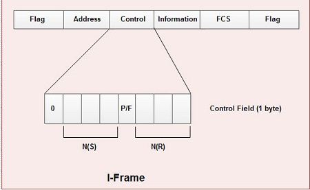
1. Information frames
• I-frames carry user’s data and control information about user’s data.
• I-frame carries user data in the information field.
• The I-frame format is shown in diagram.

• The first bit of control field is always zero, i.e. the presence of zero at this place indicates that it is I-frame.
• Bit number 2, 3 & 4 in control field is called N(S) that specifies the sequence number of the frame. Thus it specifies the number of the frame that is currently being sent. Since it is a 3.bit field, only eight sequence numbers are possible 0, 1,2,3,4,5,6, 7 (000 to 111).
• Bit number 5 in control field is P/F i.e. Poll/Final and is used for these two purposes. It has, meaning only when it is set i.e. when P/F=1. It can represent the following two cases.
(i) It means poll when frame is sent by a primary station to secondary (when address field contains the address of receiver).
(ii) It means final when frame is sent by secondary to a primary (when the address field contains the address of the sender).
• Bit number 6, 7, and 8 in control field specifies N(R) i.e. the sequence number of the frame expected in return in two-way communication.
If last frame received was error-free then N(R) number will be that of the next frame is sequence. If the last frame was not received correctly, the N(R) number will be the number of the damaged frame, asking for its retransmission.
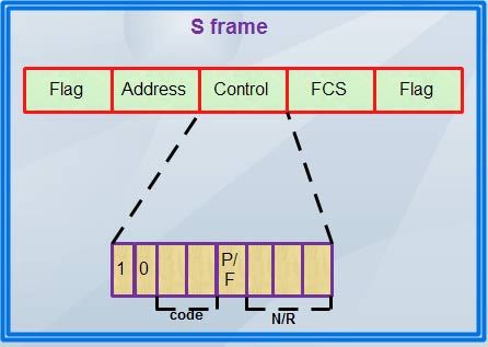
2. Supervisory frame
• S-frame carries control information, primarily data link layer flow and error controls.
• It does not contain information field.
• The format of S-frame is shown in diagram.

• The first two bits in the control field of S-frame are always 10.
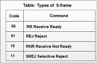
• Then there is a bit code field that specifies four types of S-frame with combination 00,01, 10, 11 as shown in table :-

1. RR, Receive Ready-used to acknowledge frames when no I-frames are availab1e to piggyback the acknowledgement.
2. REJ Reject-used by the receiver to send a NAK when error has occurred.
3. RNR Receive Not Ready-used for flow control.
4. SREJ Selective Reject-indicates to the transmitter that it should retransmit the frame indicated in the N(R) subfield.
• There is no N(S) field in control field of S-frame as S-frames do not transmit data.
• P/F bit is the fifth bit and serves the same purpose as discussed earlier.
• Last three bits in control field indicates N(R) i.e. they correspond to the ACK or NAK value.
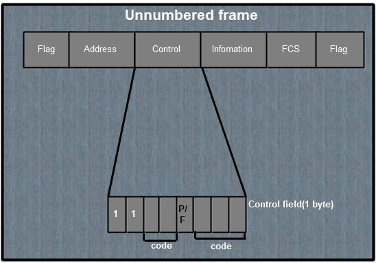
3. Unnumbered frame
• U-frames are reserved for system management and information carried by them is used for managing the link
• U-frames are used to exchange session management and control information between the two connected devices.
• Information field in U-frame does not carry user information rather, it carries system management information.
• The frame format of U-frame is shown in diagram.
• U-frame is identified by the presence of 11 in the first and second bit position in control field.
• These frames do not contain N(S) or N(R) in control field.

• U-frame contains two code fields, one two hit and other three bit.
• These five bits can create upto 32 different U-frames.
• .P/F bit in control field has same purpose in V-frame as discussed earlier.
Protocol Structure – HDLC: High Level Data Link Control
Flag – The value of the flag is always (0x7E).
Address field – Defines the address of the secondary station which is sending the frame or the destination of the frame sent by the primary station. It contains Service Access Point (6bits), a Command/Response bit to indicate whether the frame relates to information frames (I-frames) being sent from the node or received by the node, and an address extension bit which is usually set to true to indicate that the address is of length one byte. When set to false it indicates an additional byte follows.
Extended address – HDLC provides another type of extension to the basic format. The address field may be extended to more than one byte by agreement between the involved parties.
Control field – Serves to identify the type of the frame. In addition, it includes sequence numbers, control features and error tracking according to the frame type.
FCS – The Frame Check Sequence (FCS) enables a high level of physical error control by allowing the integrity of the transmitted frame data to be checked.
Related Protocols : LAPB , ISDN , X.25 , Frame Relay , SDLC
 Dinesh Thakur holds an B.C.A, MCDBA, MCSD certifications. Dinesh authors the hugely popular