Hamming code is technique developed by R.W. Hamming for error correction. This method corrects the error by finding the state at which the error has occurred.
We’ll be covering the following topics in this tutorial:
Determining the positions of redundancy bits
Till now, we know the exact number of redundancy bits required to be embedded with the particular data unit.
We know that to detect errors in a 7 bit code, 4 redundant bits are required.
Now, the next task is to determine the positions at which these redundancy bits will be placed within the data unit.
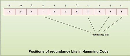
• These redundancy bits are placed at the positions which correspond to the power of2.
• For example in case of 7 bit data, 4 redundancy bits are required, so making total number of bits as 11. The redundancy bits are placed in position 1, 2, 4 and 8 as shown in fig.
 Generating parity information
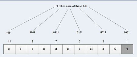
• In Hamming code, each r bit is the VRC for one combination of data bits. rl is the VRC bit for one combination of data bits, r2 is the VRC for another combination of data bits and so on.
• Each data bit may be included in more than one VRC calculation.
• rl bit is calculated using all bits positions whose binary representation includes a 1 in the rightmost position.
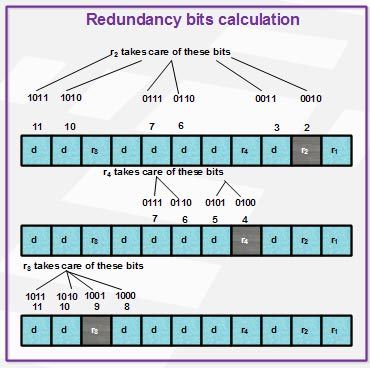
• r2 bit calculated using all the bit positions with a 1 in the second position and so on.
• Therefore the various r bits are parity bits for different combination of bits.
The various combinations are:
rl : bits 1,3,5, 7, 9, 11
r2 : bits 2, 3, 6, 7, 10, 11
r4 : bits 4, 5, 6, 7
r8 : bits 8, 9, 10, 11
 Example of Hamming Code Generation
Suppose a binary data 1001101 is to be transmitted. To implement hamming code for this, following steps are used:
1. Calculating the number of redundancy bits required. Since number of data bits is 7, the value of r is calculated as
2r > m + r + 1
24 > 7 + 4 + 1
Therefore no. of redundancy bits = 4
2. Determining the positions of various data bits and redundancy bits. The various r bits are placed at the position that corresponds to the power of 2 i.e. 1, 2, 4, 8
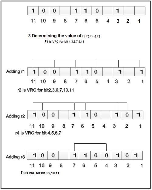

4. Thus data 1 0 0 1 1 1 0 0 1 0 1 with be transmitted.
Error Detection & Correction
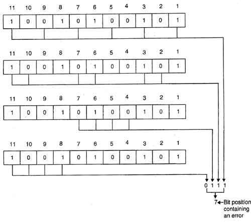
Considering a case of above discussed example, if bit number 7 has been changed from 1 to 0.The data will be erroneous.
 Data sent: 1 0 0 1 1 1 0 0 1 0 1
Data received: 1 00 1 0 1 00 1 0 1 (seventh bit changed)
The receive takes the transmission and recalculates four new VRCs using the same set of bits used by sender plus the relevant parity (r) bit for each set as shown in fig.
Then it assembles the new parity values into a binary number in order of r position (r8, r4, r2, r1).
In this example, this step gives us the binary number 0111. This corresponds to decimal 7. Therefore bit number 7 contains an error. To correct this error, bit 7 is reversed from 0 to 1.
 Dinesh Thakur holds an B.C.A, MCDBA, MCSD certifications. Dinesh authors the hugely popular