Gigabit Ethernet or GbE, is the penultimate evolution of Ethernet standard. Several improvements have been made for it to Fast Ethernet at 100 Mbit/s.
When the IEEE approved the fast Ethernet standard, fast Ethernet provided 10 time’s higher bandwidth and other new features such as full-duplex operation and auto-negotiation. It established Ethernet as a scalable technology. Now, with the emerging Gigabit Ethernet standard, it is expected to scale even further. An industry consortium called the Fast Ethernet Alliance pushed the Fast Ethernet standard. In March 1996, the IEEE 802.3 committee approved the 802.3z Gigabit Ethernet Standardization project. At that time, as many as 54 companies expressed their intentions to participate in the standardization project. The Gigabit Ethernet Alliance was formed in May 1996 by 11companies. They are 3Com Corp., Bay Networks Inc., Cisco Systems Inc., Compaq Computer Corp., Granite Systems Inc., Intel Corporation, LSI Logic, Packet Engines Inc., Sun Microsystems Computer Company, UB Networks, and VLSI Technology.
At last count, there were over 95 companies in the alliance from the networking, computer, and integrated circuit industries. IEEE issued a draft 802.3z standard in July 1997. The new Gigabit Ethernet standards are fully compatible with existing Ethernet installations. It retains Carrier Sense Multiple Access/ Collision Detection (CSMA/ CD) as the access method. It will support full duplex as well as half-duplex modes of operation. Initially, single mode and multi-mode fiber and short-haul coaxial cable supported.
Gigabit Ethernet can be deployed as a backbone in existing networks. It can be used to aggregate traffic between clients and “server farms,” and for connecting Fast Ethernet switches. It can also use for connecting workstations and servers for high bandwidth applications such as medical imaging or CAD.
Different standard solutions are the following:
• 1000BaseCX, two twisted pairs of 150 Ω;
• 1000BaseLX to a pair of optical fiber of high wavelength;
• 1000BaseSX to a pair of optical fiber of shorter wavelength;
• 1000BaseT, four pair Category 5 UTP.
The access technique to the physical medium, the CSMA / CD, is also changed. To be compatible with other versions of Ethernet, which is a basic principle, the size of the transmitted frame should be between 64 and 1500 bytes. The 64 bytes, ie 512 bits correspond to a transmission time of 512 ns. This time of 512 ns is the maximum distance from the support for a broadcast station does not disconnect before receiving a possible collision signal. This represents 100 m for a round-trip. If no hub is installed on the network, the maximum length of the physical medium is 50 m. In fact, with a connecting hub and cable portions to the couplers, the maximum distance is reduced to a few meters. To avoid this too short, standard-setters artificially increased the length of the frame to bring it to 512 bytes. The module adds padding bytes that are then removed by the receiver module.
If there is a good solution to enlarge the Gigabit network, the throughput is very low if all the frames to be transmitted have a length of 64 bytes, one eighth of the bandwidth being used in this case.
The Gigabit Ethernet accept repeaters or hubs when there are several possible directions. In the latter case, an incoming message is copied to all the output lines. Figure shows a Gigabit repeater corresponding to the IEEE 802.3z standard. The different solutions of the Gigabit Ethernet can be interconnected via a repeater or a hub.
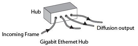
Gigabit Ethernet also operates in switched mode, in a configuration full-duplex. It can, by this means, Gigabit Ethernet interconnect them or Fast Ethernet and conventional Ethernet.
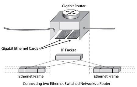
Gigabit routers are also available when back up to layer network, for example the IP layer. In this case, it is necessary to recover the IP packet for routing to the Ethernet frame. Figure shows an interconnection of two networks by a switched Gigabit router.
The management of the Gigabit network, such as Ethernet older networks is ensured by conventional techniques, essentially SNMP (Simple Network Management Protocol). The MIB (Management Information Base) Gigabit Ethernet is described in the IEEE 802.3z standard.
We’ll be covering the following topics in this tutorial:
MAC Sublayer Functions
MAC sub layer remains almost same in Gigabit Ethernet. There are two distinct approaches for medium access: half-duplex and full duplex.
• In full duplex mode
(a) There is no collision and CSMNCD is not used.
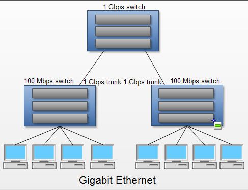
(b) Each computer is connected to central switch or other switches as shown in fig.
(c) In this mode, each switch has buffers for each input port in which data are stored until they are transmitted.
(d) The maximum length of the cable is determined by the signal attenuation in the cable.
• In Half duplex mode
(a) Switch is not used rather a hub is used.
(b) All the collisions occur in this hub.
(c) To control this, CSMA/CD approach is used.
(d) The maximum length of the network in this approach is totally dependent on the minimum frame size.
Physical layer function
Topology
• In Gigabit Ethernet, two or more stations can be connected.
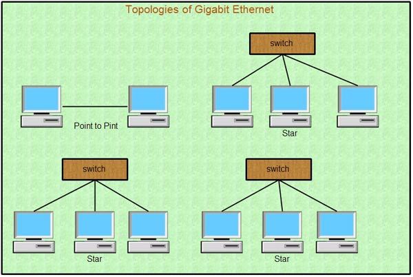
• Only two stations can be connected in point to point mode as shown in fig.
• Multiple stations (two or more) can be connected in a star topology with a switch or hub.
• The various possible implementations are shown in fig.
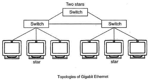
Physical layer implementation
• Two different implementation of Gigabit Ethernet are two wires and a four Wire.
• Two wire implementation uses fiber optic cable. The various two Wire implementations are 1000Base-SX, 1000Base-LX, 1000Base-CX
• Four wire implementation uses category 5 twisted pair cable. It includes 100 Base-T.
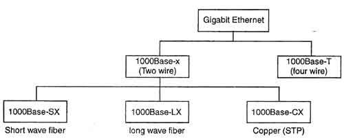
1000 Base-SX
(a) It uses multimode optical fiber with 2 wires.
(b) It uses short wave laser.
(c) The maximum length of segment supported by 1000Base-SX is 550 meters.
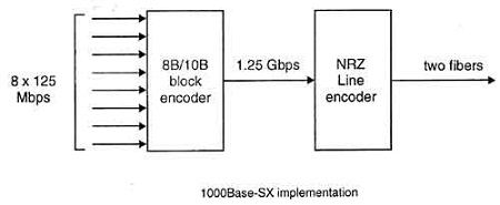
(d) It uses 8B/10B block encoding and NRZ line encoding as shown in Fig.
1000 Base-LX
• It uses multimode or single mode optical fiber (2 wires).
• It makes use of long wave laser.
• The maximum length of segment supported is 550 meters (in multimode) and 5000 meters (in single mode).
• It also uses 8B/IOB block encoding with NRZ line encoding.
1000 Base-CX
• It uses shielded twisted pair cable (2 wires) that carry electrical signal.
• The maximum length of segment supported by it is~5 meters.
• It also uses 8B/6B blocking encoding and NRZ line encoding.
1000 Base-T
• It uses category 5 UTP (4 wires).
• The maximum segment length supported is 100 meters.
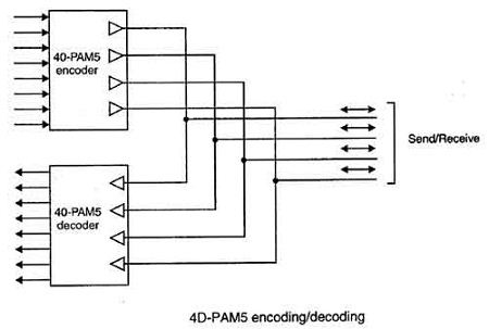
• It makes use of 4D-P AM5 encoding to reduce the bandwidth.
• In 4D-PAM 5 encoding, are four wires are evolved input and output.
• Each wire carries 250 Mbps which is in the range for cat 5 UTP cable.
Gigabit Ethernet Protocol Architecture
The Protocol stack consists of three layers. They are Physical layer, The MAC Sublayer and LLC sublayer. Figure illustrates this.
The Physical Layer
The physical layer of Gigabit Ethernet uses a mixture of proven technologies from the original Ethernet and the ANSI X3T11 Fiber Channel Specification. There are two types of physical media specifications.
They are:
- 1000BaseT
- 1000BaseX
1000BaseTis a standard for Gigabit Ethernet over long haul copper UTP. The standards committee’s goals are to allow up to 25-100 movers 4 pairs of Category 5 UTP. The 802.3ab task force has developed this standard. The 1000BaseX standard is based on the Fiber Channel Physical Layer. Fiber Channel is an interconnection technology for connecting workstations, supercomputers, storage devices, and peripherals. Fiber channel has 4-layer architecture. The lowest two layers FC-O (Interface and media) and FC-1 (Encode/Decode) are used in Gigabit Ethernet. Since Fiber channel is a proven technology, re-using it will greatly reduce the Gigabit Ethernet standard development time.
Three types of media included in the 1000BaseX standard are:
- 1000BaseSX 850 nm laser on multimode fiber.
- 1000BaseLX 1300 nm laser on single mode and multimode fiber.
- 1000BaseCX Short haul copper “twin ax” STP (Shielded Twisted-pair) cable.
The MAC (Medium Access Control) Layer
The MAC layer of Gigabit Ethernet uses the same CSMA/CD protocol as Ethernet. The maximum length of a cable segment used to connect stations is limited by the CSMA/ CD protocol. If two stations simultaneously detect an idle medium and start transmitting, a collision occurs. Gigabit Ethernet maintains the minimum and maximum frame sizes of Ethernet. Since, Gigabit Ethernet is 10 times faster than Fast Ethernet, to maintain the same frame size maximum cable length would have to be reduced to about 10 meters, which is not very useful. Instead, Gigabit Ethernet uses a bigger frame size of 512 bytes. To maintain compatibility with Ethernet, the minimum frame size is not increased, but the “carrier event” is extended. If the frame is shorter than 512 bytes, then it is padded with extension symbols. These are special symbols, which cannot occur in the regular data. This process is called Carrier Extension.
GMII (Gigabit Media Independent Interface)
The various layers of the Gigabit Ethernet protocol architecture are shown in Figure. The GMII is the interface between the MAC layer and the physical layer. It allows any physical layer to be used with the MAC layer. It is an extension of the MII (Media Independent Interface) used in Fast Ethernet. It uses the same management interface as MII It supports 10, 100, and 1000 Mbps data rates. It provides separate 8-bit wide receive and transmit data paths, so it can support both full duplex and half-duplex operation. The GMII provides 2 media status signals: one indicates presence of the carrier and the other indicates absence of collision. The Reconciliation Sublayer (RS) maps these signals to Physical Signaling (PLS) primitives understood by the existing MAC sublayer. With the GMII, it is possible to connect various media types such as shielded and unshielded twisted-pair, and single mode and multi-mode optical fiber, while using the same MAC controller. The GMII is divided into three sub layers namely PCS, PMA, and PMD.
PCS (Physical Coding Sublayer)
This is the GMII sublayer, which provides a uniform interface to the Reconciliation layer for all types of physical media. It uses 8 bit/l0 bit coding like the Fiber Channel. In this type of coding, groups of 8 bits are represented by 10 bit “code groups”. Some 10 bit code groups represent 8bit data symbols. Others are control symbols. This sublayer generates carrier Sense and Collision Detect indications. It also manages the auto negotiation process by which the NIC (Network Interface Card) communicates with the network to determine the network speed 00,100 or 1000Mbps) and mode of operation (half duplex or full duplex).
PMA (Physical Medium Attachment)
This sublayer provides a medium-independent means for the PCS to support various serial bit-oriented physical media. This layer serializes code groups for transmission and de-serializes bits received from the medium into code groups.
PMD (Physical Medium Dependent)
This sub layer maps the physical medium to the PCS. This layer defines the physical layer signaling used for various media. The GMDI (Gigabyte Medium Dependent Interface) is a part of PMD, is the actual physical layer interface. This layer defines the actual physical attachment, such as connectors for different media types.
 Dinesh Thakur holds an B.C.A, MCDBA, MCSD certifications. Dinesh authors the hugely popular