• X.25 is a standard used by many older public networks specially outside the U.S.
• This was developed in 1970s by CCITT for providing an interface between public packet-switched network and their customers.
• The packet switching networks use X.25 protocol. The X.25 recommendations were first prepared in1976 and then revised in1978,1980 and 1984.
• X.25 was developed for computer connections, used for terminal/time sharing connection.
• This protocol is based on the protocols used in early packet switching networks such as ARPANET, DATAPAC, and TRANSPAC etc.
• X.25 Packet Switched networks allows remote devices to communicate with each other across high speed digital links without the expense of individual leased lines.
• A protocol X.21 which is a physical layer protocol is used to specify the physical electrical and procedural interface between the host and network.
• The problem with this standard is that it needs digital signal rather than analog signals on telephone lines.
• So not many networks support this standard. Instead RS 232 standard is defined.
• The data link layer standard has a number of variations. It is designed for error detection and corrections.
• The network layer protocol performs the addressing, flow control, delivery confirmation etc.
• It allows the user to establish virtual circuits and send packets on them. These packets are delivered to the destination reliably and in order.
• X.25 is a connection oriented service. It supports switched virtual circuits as well as the permanent circuits.
• Packet Switching is a technique whereby the network routes individual packets of HDLC data between different destinations based on addressing within each packet.
• A switched virtual circuit is established between a computer and network when the computer sends a packet to the network requesting to make a call to other computer.
• Packets can then be sent over this connection from sender to receiver.
• X.25 provides the flow control, to avoid a fast sender overriding a slow or busy receiver.
• A permanent virtual circuit is analogous to-a leased line. It is set up in advance with a mutual agreement between the users.
• Since it is always present, no call set up is required for its use.
• In order to allow the computers which do not use the X.25 to communicate with the X.25 network a packet assembler disassembler (PAD) is used.
• PAD is required to be installed along with each computer which does not use X.25.
• X.25 defines the interface for exchange of packets between a DTE and switch data subnetwork node.
We’ll be covering the following topics in this tutorial:
Three Layers of X.25:
The X.25 interface is defined at three levels:
The three levels are:
(i) Physical layer (level 1)
(ii) Data link layer (level 2)
(iii) Packet layer (level 3).
• These three layers correspond to the three lower most layers of the ISO-OSI reference model. The physical layer takes care of the interface between a computer terminal and the link which attaches it to the packet switching node.
• The X.25 defines the interface for exchange of packets between the user’s machine (DTE) and the packet switching node to which this DTE is attached which is called as DCE.
• The three layers of X.25 interface are as shown in Fig.(a).
• At the physical level X.21 physical interface is being used which is defined for circuit switched data network. At the data link level, X.25 specifies the link access procedure-B (LAP-B) protocol which is a subset of HDLC protocol.
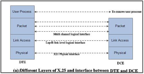
• At the network level (3rd level), X.25 defines a protocol for an access to packet data subnetwork.
• This protocol defines the format, content and procedures for exchange of control and data transfer packets. The packet layer provides an external virtual circuit service.
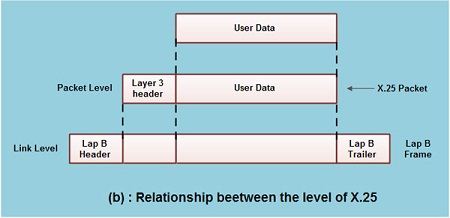
• Fig.(b) shows the relationship between the levels of x’25. User data is passed down to X.25 level 3.
• This data then appends the control information as a header to form a packet. This control .information is then used in the operation of the protocol.
• The entire X.25 packet formed at the packet level is then passed down to the second layer i.e. the data link layer.
• The control information is appended at the front and back of the packet forming a LAP-B frame. The control information in LAP-B frame is needed for the operation of the LAP-B protocol.
• This frame is then passed to the physical layer for transmission.
Virtual Circuit Service
• With the X25 packet layer, data are transmitted in packets over external virtual circuits, The virtual circuit service of X25 provides for two types of virtual circuits,
• The virtual circuit service of X25 provides for two types of virtual circuits i.e. “virtual call” and “permanent virtual circuit”.
• A virtual call is a dynamically established virtual circuit using a call set up and call clearing procedure.
• A permanent virtual circuit is a fixed, network assigned virtual circuit. Data transfer takes place as with virtual calls, but no call set up or clearing is required.
Characteristics of X.25
In addition to the characteristics of the packet switched network, X.25 has the following characteristics:
- Multiple logical channels can be set on a single physical line
- Terminals of different communication speeds can communicate
- The procedure for transmission controls can be changed.
Multiple Logical Channels can be set on a Single Physical Line
The terminal connected to the packet switched network can communicate with multiple terminals at the same time using a single physical line. This makes it possible to set multiple logical paths called logical channels on a single physical line. Multiple communications thus takes place through these logical channels. Based on the X.25 rules, 4096 logical channel can be set on a single physical line. To enable control of 4096 logical channels there are 16 logical channel groups. Each logical channel group is divided into 256 logical channels. These channel groups are known as LCGN (Logical Channel Group Number) and LCN (Logical Channel Number).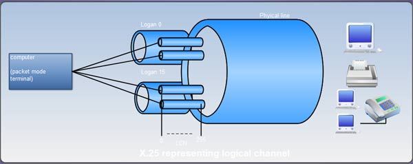
Terminals of Different Communication Speeds can communicate
As X.25 uses the store and forward method, therefore, the communication is possible. In other words, a terminal of 1.2 Kbits/s can communicate with a host computer at 9600 bits/s through the packet switched network. When the ‘telephone network or a leased line is used, this type of communication cannot be established. In other words, in these environments, the transmission speed of the sender should be the same as that of the receiver.
The reason that communication between terminals with different communication speeds is possible is that the senders and the receivers are not physically connected. Data transmission from a 1.2 Kbits/s terminal is temporarily stored in the receiving buffer of the packet switched network and the data is then passed through the network and transmitted to the host computer at 9600 bits/s.
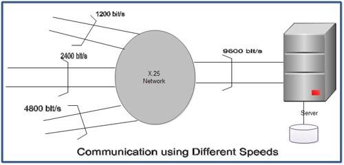 By using the above 2 features the network can be established. By applying a higher line speed to the host computer than the terminal and setting multiple logical channels, the number of lines at the computer can be reduced.
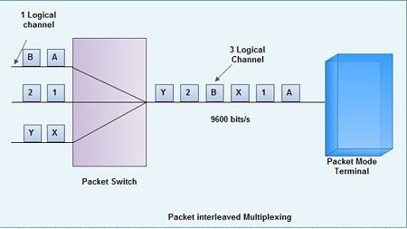
The Procedure for Transmission Controls can be changed
It is possible to change the procedure for transmission control. As we know that X.25 uses the store and forward method, therefore, all data must be once stored in the packet switched unit. By implementing a protocol conversion function to the packet switched unit can connect the devices with different transmission control (basic procedure and X.25 protocol).With the help of this method, any terminal that cannot handle packets cannot be connected to the packet switched network. A terminal that cannot handle packets is called an NPT (Non-packet mode terminal).

OSI and X.25
The X.25 standards appeared well before the OSI reference model. Hence, it was not following the 7-layer model. X.25 describes three layers, as shown in Figure.
X.21: Physical Layer
In the X.25terminology, the physical layer is called X.21interface. This interface specifies the electrical, procedural interface between the data terminal equipment and the X.25network. The RS232-C or V.35 can be used as a substitute for X.21 interface.
Link Access Layer
Link access layer of X.25 is similar to the data link layer of OSI reference model. It provides the basic point-to-point connections between the terminal and X.25 network. It also describes the data transmission and frame composition methods that X.25supports. It also provides various error control methods and flow control techniques. It defines the basic HDLC LAP-B (Link Access Procedure-B). This protocol is used for establishing virtual connections, handling flow control and releasing the connections. It also includes a mechanism for acknowledging the receipt of packets at the destination.
Packet Layer
This layer is used to setup reliable virtual connections throughout the packet-switched network and a short discussion on packet networks are given for the sake of better understanding of X.25 protocol. The following are a few components of a packet-switched network.
Packet: Packet is a unit of information that can travel independently from the source to the destination. It is packed and addressed so that no additional information is needed to deliver it. Similar to a postal envelope in the postal system, the packet travels through several devices through the network. A packet can convey many different types of information, such as commands, applications, etc.
Packet Assembler or Disassembler (PAD) In packet switching, a single block of information is broken down into many small, individually addressed packets of data. The sending station performs this and transmits them to the destination through the network. The packets are reassembled at the destination to form the original message. The device that performs this is known as a packet assembler or disassembler or PAD. The mechanism by which communication is done between two PCs, using PAD, is illustrated in Figure.
Suppose a station in LAN A is willing to send information to another station in LAN B, the following procedure is adopted. The sending station calls the local PAD and requests a virtual circuit to the remote LAN. The PAD takes data from the sending station, forming it into packets and forwards it to the X.25 network. The network-switching device routes the packets to their destination. The functions of the PAD are governed by three additional protocols. They are:
X.3: Specifies how the PAD actually assembles and disassembles the data.
X.28: Defines the interface between data terminal equipment and the PAD.
X.29: Defines the interface between data communication equipment and PAD.
Packet dispatching method Each packet in the X.25 network carries the destination address. The method by which the packet reaches its destination needs the following three components.
- • Router
- • Bridges
- • Switches
Each packet in the X.25 network contains two addresses. They are MAC address and the network address. Bridges and switches in the network use MAC address. They transmit the packet to the correct segment on the network in which the destination is present. The complete set of addresses in each network segment is available at each bridge for this purpose. Router sends the packet over predefined routes to the destination address. There are several routing algorithms used for this. Routers on the X.25 network can determine data transmission path, using connection oriented or connectionless communication method.
X.25 is a connection-oriented protocol. It establishes a connection between the sending and receiving stations before data is transmitted. However, for each connection, only one packet is transmitted, thereby, one of the major problems associated with the connection-oriented protocol is overcome. At the same time, X.25 retains the reliability of connection-oriented protocol.
Packet-switched network As the X.25 network transmits data at the rate of one packet per connection. For transmitting a complete block of data, thousands of connections are made rapidly and released. Hence, the X.25 network is known as a packet-switched network. A packet-switched network consists of a dense mesh of point-to-point connections. At a very high level, it behaves like a circuit switched network. A virtual connection is established between the sending station and the receiving station. The sending station then transmits the data to the receiving station. When the transmission is complete, the virtual circuit is cleared. The packet-switched network is similar to the one shown in Figure.
The main difference between circuit-switched and the packet-switched network is that in a circuit switched network, once a connection is established, the entire data is transmitted through that connection. But in a packet-switched network, each packet of a single message may take a different virtual circuit.
Uses of public and private X.25 networks X.25 networks provide effective solutions to many applications. They work very well, when users are willing to connect to multiple hosts for a shorter duration of time. One good example is processing of credit cards. Special card readers are used to read the information from the credit cards. The electronic transaction from the card reader is frequently carried out over an X.25 network. This permits very short messages (which include the account number, store ID, and the amount to be charged) to be sent to the concerned bank and the receipt of the transaction to be acknowledged by the bank. The X.25protocol allows this to occur without the use of costly, dedicated connections from each store to each bank that issues the credit card.
Packet-switching services can be obtained through private or public networks. Private networks are networks, whose resources (access circuits, interfaces between users’ equipments and packet switching nodes (PSNs), and the trunk circuit that connects them) are dedicated to a small group of users. Private network access is done through dedicated circuits.
Resources of a public network are owned by someone and leased on a usage basis by many users. For example, the telephone network is a public network. It is owned by DOT and leased by many subscribers under a rented basis. Access to public network is done through dial-up circuits. The tariff for usage of a public network is estimated from the amount of time the user is connected or the number of packets the user sends and receives. The choice of private and public network is based on the cost and the desired network performance.
Switched and permanent virtual circuits A virtual circuit is an end-to-end logical transmission path, through which data packets can be transmitted. Each station maintains a virtual circuit table, which contains all the virtual circuits passing through it. Virtual circuits can be established in two ways. They are permanent virtual circuit (PVC) and switched virtual circuit (SVC). The network manager can manually configure a permanent virtual circuit. Hence, at the time of transmission, no set up time is needed. The PVC provides dedicated bandwidth to a particular station. The second type of virtual circuit, switched virtual circuit (SVC) is a temporary virtual circuit set up between the sending and the receiving stations. The SVC is maintained until the transmission has been completed. It is cleared when the transmission session is over. SVC is established every time before the start of data transfer, by either the network manager or by the application. X.25 supports both types of virtual circuits.
X.25 Performance During 1976, when the X.25standard was released, it was capable of supporting a transmission speed of 64 Kbps. Unfortunately most of this bandwidth was used only for error checking. During 1992, ITU revised and issued a new X.25version, which was able to support a speed of 2.048Mbps. The France Telecom has been offering 2.08Mbps X.25 for many years. The packet based nature of the X.25 affect the performance very badly. During times when the traffic is extremely heavy, packet delivery delay is inevitable. Even though the routers are directing the packets around the congested areas, users still experience a poor performance. On the other hand packet-switching can accommodate burst of traffic over and above the maximum bandwidth however, circuit switching can accommodate inflexible and finite amount of traffic only.
X.25 protocol is highly reliable than any other protocol of this kind. Every router in the network, on receiving the packet, performs a complete check-up for the presence of errors before sending it to the next router. As a result, each node maintains a table, containing management, flow control, and error checking information against which, each packet is checked. In addition to this, the destination stations take responsibility to detect the lost or damaged packet and requests for a retransmission.
For every transmission of a packet to the next node, an acknowledgment is received from the next node in the data link layer. At the network layer, acknowledgment is sent back by the destination station to the source station as soon as the packet is received.
 Dinesh Thakur holds an B.C.A, MCDBA, MCSD certifications. Dinesh authors the hugely popular