The physical layer represents the first level of the hierarchy of the reference model. This level is responsible for transporting the bits on physical media varied. To access a support, use an access interface.

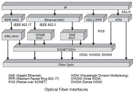
Figure shows all the modern physical layer interfaces with a physical medium, which here is the optical fiber, to transit IP packets. We see that we can encapsulate an IP packet in an ATM frame, or at least a fragment of the IP packet since the ATM frame is of limited size. Then, the ATM frame may be transmitted directly over an optical fiber, if the speed is low enough that there is no need for clock synchronization, or encapsulated in a SONET / SDH frame before being transported on fiber optics. This solution is the most developed today.
A second solution is to use the HDLC or PPP frame (point-to-point protocol) to achieve this encapsulation. To allow the synchronization of the clocks, the HDLC and PPP frames are themselves encapsulated in a SONET / SDH frame before being transmitted over the optical fiber.
Going to the left of the figure shows that the IP packet can also be encapsulated in a conventional Ethernet frame, GbE (1 Gbit/s) or 10GbE (10Gb/s). These frames are either transported directly to the optical fiber, or transmitted via SONET / SDH according to the speed, the distance of the stations, etc.
The left side of the figure shows the new generation that is beginning to be commercialized. This is a technique compatible with Ethernet, wherein the preambles Ethernet frames are increased to allow time to perform clock synchronization. This solution, standardized as IEEE 802.17, should pretty quickly replace SONET / SDH standard by its very competitive price.
The three most used frames on the physical interface is PPP, ATM and Ethernet. When considering the standards, there is often, although not an obligation, that the physical layer is itself divided into two: the PM layer (Physical Medium) sub layer lowest of physical layer, which is responsible for transporting information over the physical medium and bit synchronization and the TC layer (Transmission Convergence), high sub layer of the physical layer, which is responsible for adapting the support physics bits from frames.
The functions of the access interface to the TC sub layer include the following:
• Rate adaptation;
• Header protection;
• Delimitation of frames;
• Adaptation to transmission systems;
• Generation and recovery of the frame.
The rate adaptation is to adjust the various flows of information to the bandwidth of the physical link. To this we can add blank frames, say jam, as in the ATM cell transmission over a SONET system. Another solution is to insert padding bytes when no frame transmission is in progress. The number of stuffing byte is dependent on the time interval between two frames.
ATM cell transmission is a special case. The header contains a cell area of 1 byte whose role is to protect the 4 bytes of previous supervision. This is the HEC field (Header Error Control). It detects transmission errors and automatically makes the correction if the number of error is limited to one. When errors happen randomly, mostly with a very low probability, the error rate is excellent. Sometimes the error rate is racing when heavy disturbance during transmission signals occurs in a very short period of time, generating a series of error cells. That is why we prefer, as soon as it is discovered more than two errors on the same cell; the sensor becomes HEC rather than correcting the error, since there is every chance that the area Information is wrong.
HEC also allows delimiting the cells. The receiver is constantly in search of 4 bytes, corresponding to the HEC area. As soon as it finds a sequence that satisfies the HEC, it verifies that the corresponding areas of five cells are also correct. If that is the case, the receiver switches to synchronous mode. If he fails to frame the HEC with the following five cells, it remains in an unsynchronized state. It takes seven consecutive error detections consider that the framing is lost. The values 5 and 7 are for synchronous transmission. For asynchronous transmission, these values are set to 6 and 8 respectively.
The adaptation to the synchronous speed of the connection used to synchronize clocks the transmitter and receiver, so that the bits transmitted at the speed of the transmitter’s clock can be recovered exactly the right moment by the receiver. Both functions depend on the physical medium used to transmit the frame.
The routing of ATM cells via SONET or SDH frames is mostly reserved to operators and large networks. Two solutions are currently made: that of transporting frames over the routes operated by operators and that based on direct transport of the frame on the physical medium, without any underlying frame. The simplest solution for a quick implementation is to use links PDH (Plesiochronous Digital Hierarchy). In Europe, it is possible to route the cells on connections 2 and 34 Mbit / s, the following recommendations G.804 and G.832 of ITU-T. The cells are inserted into the body frames that circulate every 125 microseconds. An adapter is required in this insertion in order to adjust the transmission of the cells to the interface speed and insert blank cells to maintain synchronization.
 Dinesh Thakur holds an B.C.A, MCDBA, MCSD certifications. Dinesh authors the hugely popular