Shared Ethernet Networks implementing technical standard access to physical media by the IEEE 802.3 working group under the name MAC access (Medium Access Control). MAC uses a general technique called random access.
Born from research conducted in the early 1970s on random access techniques, the IEEE 802.3 standard, which later gave birth to ISO 8802.3, describes the technique of access to a shared Ethernet LAN. This is the Xerox Company that developed the first prototypes.
These may be characterized by the shared Ethernet access technique CSMA / CD, the flow rate varies from 1 to 10, 100 and 1000 Mbit / s. Beyond that, at the speed of 10 000 Mbit / s, only the switched solution is acceptable for reasons of distance.
Before going further into the details of the various Ethernet marketed products indicate the different names used by the shared Ethernet networks:
• Cheaper net – Ethernet shared that uses a thin cable (cable thin) but maintaining the same transmission capacity.
• Starlan – Shared network using the access technique CSMA / CD but on a very different topology and at speeds of 1 Mbit / s for the first generation, 10 Mbit / s for the second and 100 Mbit / s for the third.
• Fast Ethernet – Name of network to 100 Mbit / s.
• Gigabit Ethernet or GbE – Corresponds to the capacity of 1000 Mbit / s. Note the 10GbE (10 000 Mbit / s), solution for metropolitan networks, is available only Switched mode.
In fact, the number of standardized shared Ethernet networks is impressive. The box below lists them using the IEEE nomenclature.
We’ll be covering the following topics in this tutorial:
Standardized Shared Ethernet Networks
The working group suggests the technique: IEEE 802.3 corresponds to CSMA / CD, IEEE 802.3 Fast Ethernet to an extension of CSMA / CD, IEEE 802.9 CSMA an interface / CD to which is added the B channels, an Ethernet IEEE 802.11 by radio, etc. Then come the speed and modulation or not (base = baseband and broadband = broad) and finally an additional element which, originally, was the length of a strand and turned into media type:
• IEEE 802.3 10Base5 (yellow shielded coaxial cable);
• IEEE 802.3 10Base2 (Cheapernet, unshielded coaxial cable brown, Thin Ethernet); 10Broad36
• IEEE 802.3 (Ethernet broadband, CATV coaxial cable);
• IEEE 802.3 1Base5 (Starlan to 1 Mbit / s);
• IEEE 802.3 10BaseT, Twisted-Pair (son twisted pairs);
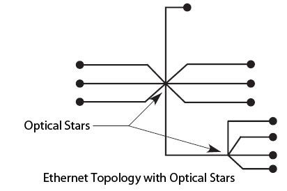
• IEEE 802.3 10Base, Fiber Optic (optical fiber):
– 10BaseFL, Fiber Link;
– 10BaseFB, Fiber Backbone;
– 10BaseFP, Fiber Passive;
• IEEE 802.3 100BaseT, twisted-pair or Fast Ethernet (100 Mbit / s CSMA / CD):
– 100BaseTX;
– 100BaseT4;
– 100BaseFX;
• IEEE 802.3 1000BaseCX (two twisted pairs of 150 Ω);
• IEEE 802.3 1000BaseLX (optical fiber pair with a high wavelength);
• IEEE 802.3 1000BaseSX (optical fiber pair with a short wavelength);
• IEEE 802.3 1000BaseT (four pairs of Category 5 UTP);
• IEEE 802.9 10BaseM (multimedia);
• 10BaseX IEEE 802.11 (wireless).
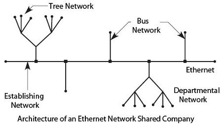
IEEE 802.12 defines the local network 100VG AnyLAN, which is compatible with Ethernet. The compatibility refers to the use of the same frame structure as in Ethernet. The access technique, however, is not compatible with the CSMA / CD. The conventional communication architecture of a shared Ethernet network includes as a backbone Ethernet network that are connected to local capillary networks.
Figure shows the general architecture of a shared Ethernet environment Business.

The capillary networks can be formed from the wiring starting from the distributor Room. Increasingly often, new buildings are prewired with an identical structure to the telephone network from the floor distributor.
The characteristics of the wirings used are the following:
• Wiring trivialized. The same cable can be used to connect a telephone handset or a computer terminal.
• Wiring not trivialized. The cable set up for communications computer workstations is different for connection of telephone handsets.
We can make various types of capillary networks from the cable system. The choice of the quality of the cable is important in case of distance constraint. It is best to limit the distance between the equipment room and the periphery to fifty meters. The American ANSI recommendation proposes a limit of 295 feet (90 m).
The current trend is to set up a cabling commonplace since the integration of telephony and computers with VoIP (Voice over IP) is an inevitable direction.
Features shared Ethernet networks
The characteristics of the shared Ethernet networks are described in the standard ISO 8802.3 10Base5.
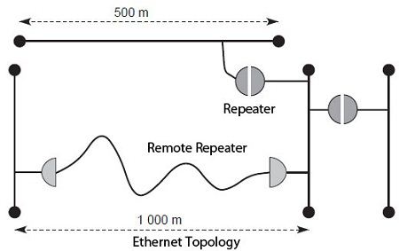
The topology of an Ethernet network 500 comprises m strands maximum, interconnected to each other by repeaters. These transponders are active elements that retrieve a signal and retransmit after regeneration. Computer hardware connections can be made every 2.5 m, allowing up to 200 connections per strand.
In many products, the specifications state that the signal should never cross over two repeaters and one may be removed. The signal regeneration is performed once crossed a line with a range of 1000 m. The maximum length is 2.5 km, corresponding to three strands of 500 m and a remote repeater. This limitation of the distance to 2.5 kilometers however, is not a feature of the standard. We will see a little further than we can overcome these constraints to three repeaters and reach a total distance of about 5 km.

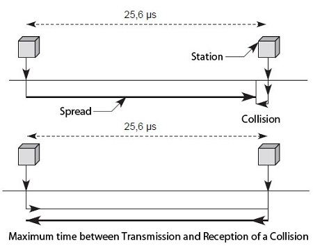
The only constraint to be taken into account is the maximum time elapsing between the transmission and reception of the signal in the far coupler. This time does not exceed a value of 25.6 microseconds. Indeed, in a collision, the time before retransmission is a multiple of 51.2 microseconds. To avoid another collision between two frames reissued different time slices, it has to flow up 51.2 microseconds from the time of issue and that of listening to the collision. The time to go is a maximum of 25.6 microseconds, if the collision takes place just before the arrival of the remote signal. It is also up 25.6 microseconds for the collision to the initial station. In addition, the length of a frame must be at least equal to the round-trip time, so that the transmitter can record a collision. This minimum length is 64 bytes. 51.2 microsecond’s minimum time we recover propagation noting that 64 bytes equivalent to 512 bits, which, at the speed of 10 Mbit / s, require a time of 51.2 microseconds show.

The access technique to the transmission medium is Ethernet chosen by random access with detection of persistent type carrier. If the transceiver module detects the presence of other programming on the cable, the Ethernet module can issue frame.
If a collision occurs, the transceiver modules send an interrupt signal to the collision and initialize the retransmission procedure. The interruption of the collision occurs after the transmission of a binary sequence, called stuffer sequence (jam), which checks that the duration of the collision is sufficient to be observed by all transmission stations involved in the collision.

It is necessary to define several parameters to explain the recovery procedure on a collision. The maximum round trip time is the time that elapses between the two most distant points of the local network, from the transmission of a frame until the return of a collision signal. This value is 51.2 microseconds or 512 times a bit emission, or 512 elementary times. The jam sequence lasts 48 elementary times. Ethernet also defines a “time slice” which is the minimum time before retransmission (51.2 ms). Before retransmission time also depends on the number n of already performed collisions. The random delay in retransmission Ethernet is a multiple of the time slot after the time r × 51.2 microseconds, where r is a random number such that 0 ≤ r <2k, where k = min (n, 10) and n is the number of already performed collisions. If, after 16 trials, the frame is still colliding, the transmitter abandons its transmission. A recovery takes place from the higher level protocols.
When two frames collide for the first time, they have an even chance to come again in collision: r = 1 or 0. Although the retransmission algorithm, or back-off, does not seem optimal, this is the technique that works best because it is better to try to fill the transmission medium rather than waiting too long time and lose speed.
A simple calculation shows that the retransmission time, after ten successive collisions account for only a few milliseconds, that is to say even very short time. CSMA / CD is a probabilistic technique, it is difficult to determine the time elapsed between the arrival of the frame in the coupling of the transmitter and the departure of the frame of the receiver module to the recipient. This time depends on the number of collisions and, indirectly, the number of stations of the network load and the average distance between two stations. The greater the delay, the greater the risk of collision increases.
All calculations reported herein refer to an Ethernet network at 10Mbit/s. If we increase the network speed by multiplying by 10 the speed (100 Mbit/s), the maximum distance between the two farthest stations is also divided by 10, and so on, so that we get maintaining the same minimum frame length:
10 Mbit / s => 5 km
100 Mbit / s => 500 m
1 Gbit / s => 50 m
10 Gbit / s => 5 m
Distances are without the existence of repeaters or hubs, which require a crossing time and diminish accordingly the maximum distance. To counter this problem, two solutions can be implemented: increase the size of the Ethernet frame or upgrade to switching. Ethernet 1 Gbit/s uses a minimal frame of 512 bytes, allowing it to return to a maximum distance of 400 m. The network to 10 Gbit/s using only switching.
 Dinesh Thakur holds an B.C.A, MCDBA, MCSD certifications. Dinesh authors the hugely popular