A pair of wires twisted together form a twisted pair. They have more noise immunity than the two-wire open lines. Each wire is insulated and has thickness in the order of 0.016 inches to 0.015 inches. [Read more…] about 10BASE T – What is 10BASET (Twisted Pair Ethernet) ?
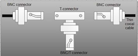
BNC/T-connector
The Figure shows the BNC connector and T-connector. The BNC connector and T-connector, these are simple connectors that cannot exchange data. An NIC and T-connector must be directly connected.
[/vc_column_text][/vc_column][/vc_row]
10 Base 2 – What is 10Base2 (Thin Net/Black Ethernet)
This is also known as 10Base2, uses coaxial of thinner gauge of 5 mm in diameter and bus topology as in the case of 10Base5 so that multiple computers can be connected to a single transmission line. Primarily it was used in office environments. The thinner cable is less costly to acquire and deploy, although its performance is less in terms of transmission distance. Because of its cost it is sometimes called as cheapnet. 10Base2 signifies in the same manner as 10Bases5 except 2 is signified here as 200 meters maximum segment length (actually 185 meters). [Read more…] about 10 Base 2 – What is 10Base2 (Thin Net/Black Ethernet)
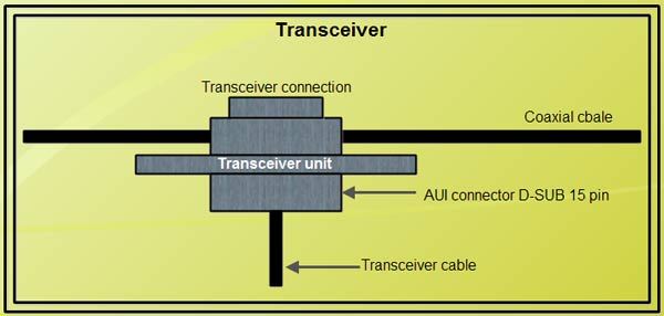
Transceiver – What is Transceiver?
The transceiver exchanges data signals handled by the NIC and electric signals sent over a transmission line. A I5-pin D-SUB connector is used to connect transceivers and transceiver cables. Multiport transceiver supports more than one NIC.
[/vc_column_text][/vc_column][/vc_row]
10 Base 5 – What is 10Base5 (Thick Net/Yellow Ethernet)?
This uses traditional thick baseband coaxial cable in bus topology to connect multiple computers as shown. This single transmission line is called a segment. A coaxial cable 10 mm in diameter, known as a thick coaxial cable is used as a transmission line. A terminator is connected at each end of the cable. Note that proper data communication cannot be assured even if one of these terminators is missing or not properly connected. [Read more…] about 10 Base 5 – What is 10Base5 (Thick Net/Yellow Ethernet)?
Lan Operating Systems
A LAN Operating System, or Network Operating System (NOS), is software that provides the network with multi-user, multitasking capabilities. The operating system facilitates communications and resource sharing, thereby providing the basic framework for the operation of the LAN. The operating system consists of modules that are distributed throughout the LAN environment. Some NOS modules reside in servers, while other modules reside in the clients. [Read more…] about Lan Operating Systems
Media Access Control (MAC layer) – Definition
Definition: Media access control (MAC) and logical link control (LLC) are the sublayers of the data link layer (Layer 2) in OSI Reference Model. ‘MAC’ is also refer to as MAC layer. It use MAC protocols to provides unique addressing identification and channel access control mechanism for network nodes to communicate with other nodes across a shared channel. [Read more…] about Media Access Control (MAC layer) – Definition
Broadband versus Baseband
Broadband A communications medium that can carry a wide range of signal frequencies, typically from audio up to video frequencies. In telecommunications the significance of a broadband system is that it can carry television and videoconferencing data as well as voice calls. A broadband medium can be made to carry many signals at once by apportioning its total bandwidth into many independent channels, each of which carries only a specific range of frequencies. In contrast, a BASEBAND can carry only a single channel. ATM, ADSL and Cable TV are all broadband media, while standard ISDN barely qualifies.
There exist two LAN transmission options, Baseband and Broadband. Baseband LANs, which is the most prevalent by far, is a Single-channel system that supports a single transmission at any given time.
Broadband LANs, which are most unusual, support multiple transmissions via multiple frequency channels.
Broadband LANs
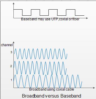
Broadband LANs are Multichannel, analog LANs as shown in Figure. typically based on coaxial cable as the transmission medium, although fiber optic cable is also used. Individual channels offer bandwidth of 1 to 5 Mbps, with 20 to 30 channels typically supported. Aggregate bandwidth is as much as 500 MHz. Its characteristics are:
• Digital signal modulated onto RF carrier (analog)
• Channel allocation based on FDM
• Head-End for bidirectional transmission
• Stations connected via RF modems, Le. radio modems accomplish the digital-to-analog conversion process, providing the transmitting device access to an analog channel.
Advantages
Data, voice and video can be accommodated on broadband channel
• Greater distances
• Greater bandwidth.
Disadvantages
• Cable design
• Alignment and maintenance
• High cost, requires modems
• Lack of well-developed standards.
Some broadband LANs are referred to as IOBroadband36 where 10stands for 10Mbps, Broadband for multichannel and 36 for 3600 meters maximum separation between devices.
Baseband LANs
Baseband LAN is single channel, supporting a single communication at a time as shown in Figure. They are digital in nature. Total bandwidth of I to 100Mbps is provided over coaxial cable, UTP, STP, or fiber optic cable. Distance limitations depend on the medium employed and the specifics of the LAN protocol. Baseband LAN physical topologies including ring, bus, tree, and star.
Baseband LANs are by far the most popular and the most highly standardized. Ethernet, Token Passing, Token Ring and FDDI LANs are all baseband. They are intended only for data, as data communications is, after all, the primary reason for the existence of LANs. The characteristics of this system may be summarized as follows:
• Unmodulated digital signal
• Single channel
• Bidirectional propagation of signal
• Stations connected, via T connectors
• No need of modems – low cost installation.
Advantages
• Simplicity
• Low cost
• Ease of installation and maintenance
• High rates.
Disadvantages
• Limited distances
• Data and voice only.
What is protocol? and its types – Definition
Protocol Definition: It is a digital language through which we communicate with others on the Internet. protocol meaning is that it a set of mutually accepted and implemented rules at both ends of the communications channel for the proper exchange of information. By adopting these rules, two devices can communicate with each other and can interchange information. We can’t even think of using the Internet without Protocols. Each protocol is defined in different terms and different use with unique name. Message travel from sender to receiver via a medium (The medium is the physical path over which a message travels) using a protocol. [Read more…] about What is protocol? and its types – Definition
Star Topologies – What is Star Topologies?
The distinguishing feature of star topology is that all nodes are joined at a single point, as shown in Figure. This single point is called as a central node, hub, or switch, to which all other devices are attached directly, generally via UTP or STP. This topology is frequently used for networks in which control of the network is located in the central node. This method is optimal when the bulk of communication is between the central and outlying nodes. If traffic is high between outlying nodes, an undue switching burden is placed on the central node. [Read more…] about Star Topologies – What is Star Topologies?
Ring Topologies – What is Ring Topologies?
The ring architecture is a distributed architecture, with minimal connectivity and a topology of two links connected to every node as shown in Figure and forms unbroken circular configuration. Figure shows a network laid out in a physical ring, or closed loop, configuration. Transmitted messages travel from node to node around the ring. Each node must be able to recognize its own address in order to accept messages. [Read more…] about Ring Topologies – What is Ring Topologies?
What is Bus Topology? Advantages and Disadvantages of Bus Network
Bus Topology is multipoint electrical circuits that can be implemented using coaxial cable, UTP, or STP. Data transmission is bidirectional, with the attached devices transmitting in both directions. While generally operating at a raw data rate of 10 Mbps, actual throughput is much less. [Read more…] about What is Bus Topology? Advantages and Disadvantages of Bus Network
Cell Switching (ATM)
Cell switching is associated with Asynchronous Transmission Mode (ATM) which is considered to be a high speed switching technology that attempted to overcome the speed problems faced by the shared media like Ethernet and FDDI. Cell switching uses a connection-oriented packet-switched network. [Read more…] about Cell Switching (ATM)
Comparison between Virtual Circuit and Datagram
Datagram is better if numbers of packets are not very large. As it is a connectionless service there is no need to prior call set up. Therefore, It is more flexible and provides alternate route to avoid the congested part of the network. [Read more…] about Comparison between Virtual Circuit and Datagram
Difference between Virtual Circuit (VC) and Permanent Virtual Circuit (PVC)
Virtual Circuit (VC) – In this type connection, DTE selects the links to be used before communication to connect a receiver just as in the case of telephone network. In other words, we may say that a pre-planned route established before any packets are sent. A communications arrangement in which data from a source user may be passed to a destination user over various real circuit configurations during a single period of communication and the Information about the routing of packets is stored in all nodes throughout the set-up phase. Virtual circuits generally set up on a per connection basis and are disconnected when the connection is terminated and after that, the information in the network is erased. However, a permanent virtual circuit can be established as an option to provide a dedicated link between two facilities. [Read more…] about Difference between Virtual Circuit (VC) and Permanent Virtual Circuit (PVC)
Logical Channels
The terminal connected to the packet switched network can communicate with multiple terminals at the same time using a single physical line. This makes it possible to set multiple logical paths called logical channels on a single physical line. [Read more…] about Logical Channels
Point-to-point Connections
The point-to-point scheme provides separate communication channels for each pair of computers. When more than two computers need to communicate with one another, the number of connections grows very quickly as number of computer increases. Above figure illustrates that two computers need only one connection, three computers need three connections and four computers need six connections.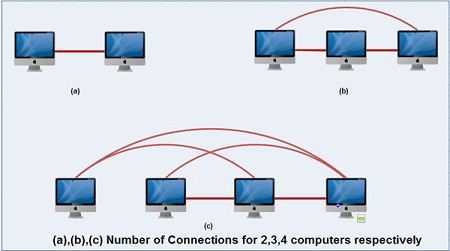 [Read more…] about Point-to-point Connections
What is Metropolitan Area Network (MAN)? – Definition
The MAN network (Metropolitan Area Network) is a high-speed network (broadband) that covers larger geographic area such as city (tens of kilometers) or districts than local area network (LAN) but smaller than wide area network (WAN) and providing the ability to integrate multiple services through the transmission of data, voice, and video, on transmission media such as copper, fiber optics, and microwaves. [Read more…] about What is Metropolitan Area Network (MAN)? – Definition
Evolution of Computer Networks
The term computer networks resulted from the ‘combination of two major areas, namely computers and communications. 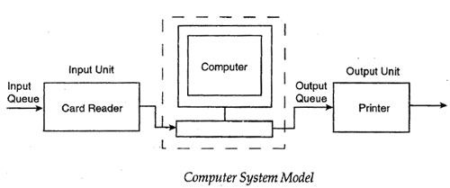 [Read more…] about Evolution of Computer Networks
Need For Computer Networks
The term network is defined as a set of computers of different types, terminals, telephones, and other communication equipments, connected by data communication links, which allow the network components to work together. The network components may be located within a small area or spread over many remote locations. In any case, data communications hold the network together.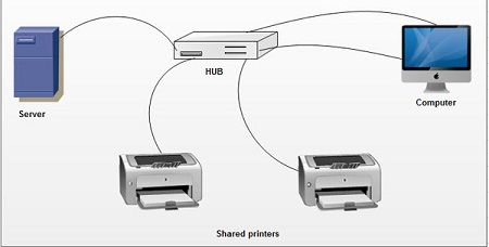 [Read more…] about Need For Computer Networks
Wavelength Division Multiplexing (WDM)
Fiber optic technology is considered to meet the ever-increasing demand of bandwidth for the exchange of information and Wavelength Division Multiplexing (WDM) provides solutions for the ever-increasing demand of bandwidth through optical networks. In optical communication” the analog of FDM is referred to as wavelength-division multiplexing (WDM). [Read more…] about Wavelength Division Multiplexing (WDM)
Code Division Multiplexing (CDM)/Spread Spectrum
CDM is widely used in so-called second-generation (2G) and third-generation 3G wireless communications. The technology is used in ultra-high-frequency (UHF) cellular telephone systems in the 800-MHz and 1.9-GHz bands. This is a combination of analog-to-digital conversion and spread spectrum technology. [Read more…] about Code Division Multiplexing (CDM)/Spread Spectrum
Statistical Time Division Multiplexing (STDM)
In case of TDM, time slots are allocated to channels, even if they have no information to transmit. This is just wastage of the bandwidth and to overcome this inefficiency of standard TDM, a technique known as STDM has been developed where time is allocated to lines only when it is required. This is achieved with the use of intelligent devices that are capable of identifying when a terminal is idle. [Read more…] about Statistical Time Division Multiplexing (STDM)
Frequency Division Multiplexing
In Frequency Division Multiplexing (FDM), multiple channels are combined onto a single aggregate signal for transmission. The channels are separated in the aggregate by their frequency. It is explained in the Figure where a frequency dimension is subdivided into several non-overlapping frequency bands. Each channel ci is allotted its own frequency band as depicted in Figure. [Read more…] about Frequency Division Multiplexing
What are Difference between Circuits, Channels and Multichanneling?
A circuit is a path between two or more points along which an electrical current flows. In data communication, we may consider a circuit as a specific path between two or more points along which signals can be carried. The signals may be analog, binary or digital. It has been shown in the Figures, wherein the link between PC and modem, link between modem and CTO and so on constitutes a circuit. [Read more…] about What are Difference between Circuits, Channels and Multichanneling?
Modem- Classification of Modems
Modem word came from the combination of two words modulator and demodulator. A modem is a hardware device that enables the computers to transmit data over cable or satellite connection.A modem converts signals between modulator and demodulator vice versa. The outgoing digital signals from a computer a modem can modulates to an analog signals and in the demodulation in reverse analog signal are converts back to a digital signal.The modems can be classified according to their characteristics as below: [Read more…] about Modem- Classification of Modems
Encoding Techniques and Codec
It is required that information must be encoded into signals before it can be transported across communication media. In more precise words we may say that the waveform pattern of voltage or current used to represent the 1s and 0s of a digital signal on a transmission link is called digital to digital line encoding. There are different encoding schemes available:
Digltal-to-Digltal Encoding
It is the representation of digital information by a digital signal.
 There are basically following types of digital· to-digital encoding available like:
- Unipolar
- Polar
- Bipolar.
Unipolar
Unipolar encoding uses only one level of value 1 as a positive value and 0 remains Idle. Since unipolar line encoding has one of its states at 0 Volts, it’s also called Return to Zero (RTZ) as shown in Figure. A common example of unipolar line encoding is the 11’L logic levels used in computers and digital logic.
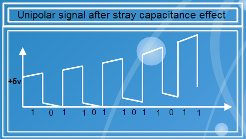
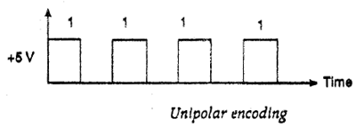 Unipolar encoding represents DC (Direct Current) component and therefore, ca.’1nottravel through media such as microwaves or transformers. It has low noise margin and needs extra hardware for synchronization purposes. It is well suited where the signal path is short. For long distances, it produces stray capacitance in the transmission medium and therefore, it never returns to zero as shown in Figure.
Polar
Polar encoding uses two levels of voltages say positive and negative. For example, the RS:232D interface uses Polar line encoding. The signal does not return to zero; it is either a positive voltage or a negative voltage. Polar encoding may be classified as non·return to zero (NRZ), return to zero (RZ) and biphase. NRZ may be further divided into NRZ·L and NRZ·I. Biphase has also two different categories as Manchester and Differential Manchester encoding. Polar line encoding is the simplest pattern that eliminates most of the residua! DC problem. Figure shows the Polar line encoding. It has the same problem of synchronization as that of unipolar encoding. The added benefit of polar encoding is that it reduces the power required to transmit the signal by one-half.

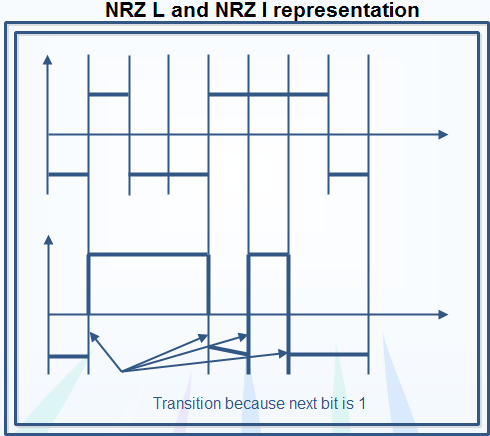
Non-Return to Zero (NRZ)
In NRZ·L, the level of the signal is 1 if the amplitude is positive and 0 in case of negative amplitude.
In NRZ·I, whenever a positive amplitude or bit I appears in the signal, the signal gets inverted,
Figure explains the concepts of NRZ-L and NRZ·I more precisely.
Return to Zero (RZ)
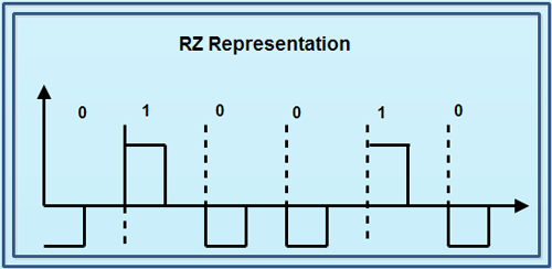
RZ uses three values to represent the signal. These are positive, negative, and zero. Bit 1is represented when signal changes from positive to zero. Bit 0 is represented when signal changes from negative to zero. Figure explains the RZ concept.
 Biphase
Biphase is implemented in two different ways as Manchester and Differential Manchester encoding.
In Manchester encoding, transition happens at the middle of each bit period. A low to high transition represents a 1 and a high to low transition represents a 0.In case of Differential Manchester encoding, transition occurs at the beginning of a bit time, which represents a zero.
These encoding can detect errors during transmission because of the transition during every bit period. Therefore, the absence of a transition would indicate an error condition. They have no DC component and there is always a transition available for synchronizing receives and transmits clocks.
Bipolar
Bipolar uses three voltage levels. These are positive, negative, and zero. Bit 0 occurs at zero level of amplitude. Bit 1 occurs alternatively when the voltage level is either positive or negative and therefore, also called as Alternate Mark Inversion (AMI). There is no DC component because of the alternate polarity of the pulses for Is. Figure describes bipolar encoding.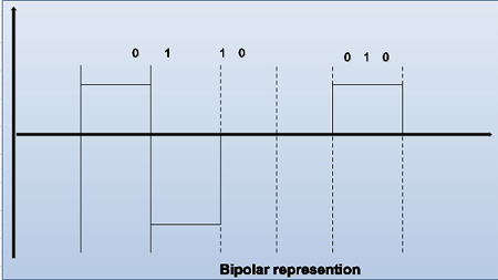 Analog to Digital
Analog to digital encoding is the representation of analog information by a digital signal. These include PAM (Pulse Amplitude Modulation), and PCM (Pulse Code Modulation).
Digital to Analog
These include ASK (Amplitude Shift Keying), FSK (Frequency Shift Keying), PSK (Phase Shift Keying), QPSK (Quadrature Phase Shift Keying), are QAM (Quadrature Amplitude Modulation).
Analog to Analog
These are Amplitude modulation, Frequency modulation and Phase modulation techniques,
Codec’s (Coders and Decoders)
Codec stands for coders/decompression in data communication. The reverse conversion of analog to digital is necessary in situations where it is advantageous to send analog information across a digital circuit. Certainly, this is often the case in carrier networks, where huge volumes of analog voice are digitized and sent across high capacity, digital circuits. The device that accomplishes the analog to digital conversion is known as a codec. Codec’s code an analog input into a digital format on the transmitting side of the connection, reversing the process, or decoding the information on the receiving side, in order to reconstitute the analog signal. Codec’s are widely used to convert analog voice and video to digital format, and to reverse the process on the receiving end.
Infrared Transmission– What is a Infrared Transmission?
Infrared light transmissions have existed for many years and their use having been limited to TV remote controls and wireless slide projector remote controls. However, they now are assuming a position of some, if still limited, importance. Infrared systems use the infrared light spectrum to send a focused light beam to a receiver, much, as would a microwave system, although no reflective dish is used. Rather, pair of lenses is used, with a focused lens employed in the transmitting device and a collective lens in the receiving device as shown in Figure. Infrared is an airwave, rather that a conducted transmission system. Although generally used in short-haul transmission, they do offer substantial bandwidth, but with risks of interference. [Read more…] about Infrared Transmission– What is a Infrared Transmission?
Satellite Communication – What is a Satellite Communication?
Satellite radio, quite simply, is a non-terrestrial microwave transmission system utilizing a space relay station. Satellites have proved invaluable in extending the reach of voice, data, and video communications around the globe and into the most remote regions of the world. Exotic applications such as the Global Positioning System (GPS) would have been unthinkable without the benefit of satellites. [Read more…] about Satellite Communication – What is a Satellite Communication?
Microwave Transmission – What is a Microwave Transmission?
Microwave radio, a form of radio transmission that use. Ultra-high frequencies developed out of experiments with radar (radio detecting and ranging) during the period preceding World War II. There are several frequency ranges assigned to microwave systems, all of which are in the Giga Hertz (GHz) range and the wavelength in the millimeter range. This very short wavelength gives rise to the term microwave. Such high frequency signals are especially susceptible to attenuation and, therefore must be amplified or repeated after a particular distance. [Read more…] about Microwave Transmission – What is a Microwave Transmission?