Modem is abbreviation for Modulator – De-modulator. Modems are used for data transfer from one computer network to another computer network through telephone lines. The computer network works in digital mode, while analog technology is used for carrying massages across phone lines. [Read more…] about Modem: What is a Modem? Types of Modems
What is packet
A packet is the unit of data that is routed between an origin of computer or device to another on the Internet or any other packet-switched network. When any file (e-mail message, HTML file, Graphics Interchange Format file, Uniform Resource Locator request, and so forth) is sent from one place of network to another place of network on the Internet, the Transmission Control Protocol (TCP) layer of TCP/IP of network.
What is in a packet?
Divides the file into “chunks” of an efficient size for routing. Each of these packets is separately numbered, data size, and other useful information and includes the Internet address of the destination. The individual packets for a given file may travel different routes through the Internet. When they have all arrived, they are reassembled into the original file (by the TCP layer at the receiving end).
A packet-switching scheme is an efficient way to handle transmissions on a connectionless networking such as the Internet. An alternative scheme, circuit-switched, is used for networks allocated for voice connections. In circuit-switching, lines in the network are shared among many users as with packet-switching, but each connection requires the dedication of a particular path for the duration of the connection.
“Packet” and “datagram” are similar in meaning. A protocol similar to TCP, the User Datagram Protocol (UDP) uses the term datagram.
Structure of a Data Packet
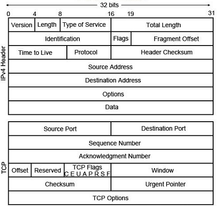
The structure of a Data Packet depends on the protocol it used. The header section of packet keeps overhead information, the service, and other transmission related data.
• Source address: which is the IP address of sender.
• Destination address: which is the IP address of recipient.
• Sequence number: A packet number that puts in order such that when they are reassembled on the destination.
Difference Client Computer and workstation and Dumb Terminals
Client Computer: A personal computer in networking that connects to the server and uses the network services to perform user’s tasks is a client computer.
Workstation: A workstation is a node in networking that is more powerful and can handle local information processing or graphics processing. A workstation usually has an inexpensive, small hard disk to carry out local tasks. Some workstations that have no disk drive of their own is known as diskless-workstation or dumb terminals. They terminals completely rely on LAN for their access. Network operating system lets the node work as if all the resources at the server belong to the node itself.
The term workstation also reference to a mainframe terminal on a LAN. A workstation is faster personal computer. It has greater multitasking capability because of additional RAM and higher-speed graphics adapters.
Dumb Terminals: Those Workstations that have no disk drive of their own and rely completely on LAN for their access are called dumb terminals. The network operating system lets these terminals work as if all the resources at the server belong to the workstation itself
Ethernet topology – What is an Ethernet topology? How an Ethernet Worked?
The IEEE 802.3 standard is popularly called as Ethernet. It is a bus based broadcast network with decentralized control. It can operate at 10 Mbps or 100 Mbps or above. Computers on an Ethernet can transmit whenever they want to do so. If two or more machines transmit simultaneously, then their packets collide. Then the transmitting computers just wait for an arbitrary time and retransmit their signal. There are various technologies available in the LAN market but the most popular one of them is Ethernet.
The Ethernet topology was developed at the University of Hawaii to connect computers on the various Islands. It was radio based design. Ethernet is one of the most popular Computer Network or LAN technologies in use today covering more than 85% of the computer networks. Ethernet system consists of three basic elements:
1. The physical medium use to carry Ethernet signals between computers on the network
2. A set of rules (protocols) embedded in each Ethernet interface that will decide how multiple computers on the network will have access to the data on the medium.
3. An Ethernet frame that consists of a standardized set of bits used to carry data over the system.
The operation of Ethernet can be described in simple terms as follows:
Each computer on the Ethernet Network, also known as a node, operates independently of all other nodes. All nodes attached to an Ethernet are connected to a shared medium over which the Ethernet signals travel serially, one data bit at a time.
To send data a station first listens to the channel and when the channel is idle the station transmits its information in the form of an Ethernet frame, or packet. The Ethernet rules (protocol) are defined in such a way that every node gets a fair amount of frame transmission opportunity.
As each Ethernet frame is sent out on the shared medium, the Ethernet interfaces inside the node look at the destination address. The interfaces compare the destination address of the frame with their own address. The Ethernet interface with the same address as the destination address in the frame will read the entire frame and all other network interfaces will ignore the information.
Medium Access Control of Ethernet
The set of rules which ensures that every node in an Ethernet gets a fair amount of frame transmission opportunity, are called the “Medium Access Control” mechanism. The Medium Access Control mechanism is based on a system called Carrier Sense Multiple Access with Collision Detection (CSMD/CD).
Ethernet Frame
The heart of Ethernet system is the Ethernet Frame, which is used to deliver information between the computers. The frame consists of a set of bits organized into several fields. These fields include address fields, a data field and an error checking field that checks the integrity of the bits in the frame to make sure that the frame has arrived intact.
Advantages of Ethernet
Ethernet’s major advantages are:
1. It is an inexpensive way to achieve high speed LAN transmissions (10 to 100 MB/s)
2. It is a proven technology that supports various writing configurations.
3. It works well with a large number of LAN and micro-to-mainframe applications.
4. It is easy to install.
Disadvantages of Ethernet Cabling
The Ethernet cabling ahs the following disadvantages:
1. Ethernet is not a high-level performer in high-load environments. This protocol (CSMA/CD: Carrier Sense Multiple Access/Collision Detection) can slow down dramatically if hundreds of workstations are competing for the same cabling trunk.
2. Its linear bus cabling system can sometimes make it difficult to isolate problems.
What is IEEE 802.4 Protocol? Token Bus
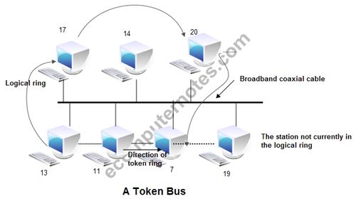
IEEE 802.4 Token Bus: In token bus Computer network station must have possession of a token before it can transmit on the computer network. The IEEE 802.4 Committee has defined token bus standards as broadband computer networks, as opposed to Ethernet’s baseband transmission technique. Physically, the token bus is a linear or tree-shape cable to which the stations are attached.
The topology of the computer network can include groups of workstations connected by long trunk cables. Logically, the stations are organized into a ring. These workstations branch from hubs in a star configuration, so the network has both a bus and star topology. Token bus topology is well suited to groups of users that are separated by some distance. IEEE 802.4 token bus networks are constructed with 75-ohm coaxial cable using a bus topology. The broadband characteristics of the 802.4 standard support transmission over several different channels simultaneously.
When the logical ring is initialized, the highest numbered station may send the first frame. The token and frames of data are passed from one station to another following the numeric sequence of the station addresses. Thus, the token follows a logical ring rather than a physical ring. The last station in numeric order passes the token back to the first station. The token does not follow the physical ordering of workstation attachment to the cable. Station 1 might be at one end of the cable and station 2 might be at the other, with station 3 in the middle.
In such a case, there is no collision as only one station possesses a token at any given time. In token bus, each station receives each frame; the station whose address is specified in the frame processes it and the other stations discard the frame.
Physical Layer of the Token Bus
The conventional 75 ohm coaxial cable used for the cable TV can be used as the physical layer of the token bus. The different modulation schemes are used. They are, phase continuous frequency shift keying, phase coherent frequency shift keying, and the multilevel duo binary amplitude-modulated phase shift keying. Signal speeds in the range 1 Mbps, 5 Mbps, and 10 Mbps are achievable. The physical layer of the token bus is totally incompatible to the IEEE 802.3 standard.
MAC Sublayer Function
• When the ring is initialized, stations are inserted into it in order of station address, from highest to lowest.
• Token passing is done from high to low address.
• Whenever a station acquires the token, it can transmit frames for a specific amount of time.
• If a station has no data, it passes the token immediately upon receiving it.
• The token bus defines four priority classes, 0, 2, 4, and 6 for traffic, with 0 the lowest and 6 the highest.
• Each station is internally divided into four substations, one at each priority level i.e. 0,2,4 and 6.
• As input comes in to the MAC sublayer from above, the data are checked for priority and routed to one of the four substations.
• Thus each station maintains its own queue of frames to be transmitted.
• When a token comes into the station over the cable, it is passed internally to the priority 6 substation, which can begin transmitting its frames, if it has any.
• When it is done or when its time expires, the token is passed to the priority 4 substation, which can then transmit frames until its timer expires. After this the token is then passed internally to priority 2 substation.
• This process continues until either the priority 0 substation has sent all its frames or its time expires.
• After this the token is passed to the next station in the ring.
Frame format of Token Bus
The various fields present in the frame format are
1. Preamble: This. Field is at least 1 byte long. It is used for bit synchronization.

2. Start Delimiter: This one byte field marks the beginning of frame.
3. Frame Control: This one byte field specifies the type of frame. It distinguishes data frame from control frames. For data frames it carries frame’s priority. For control frames, it specifies the frame type. The control frame types include. token passing and various ring maintenance frames, including the mechanism for letting new station enter the ring, the mechanism for allowing stations to leave the ring.
4. Destination address: It specifies 2 to 6 bytes destination address.
5. Source address: It specifies 2 to 6 bytes source address.
6. Data: This field may be upto 8182 bytes long when 2 bytes addresses are used & upto 8174 bytes long when 6 bytes address is used.
7. Checksum: This 4 byte field detects transmission errors.
8. End Delimiter: This one byte field marks the end of frame.
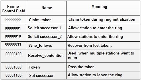
The various control frames used in token bus are:
Maintaining the Ring
Control frames Control frames are frames used for controlling and maintaining the logical ring. The format is same as the format specified in Figure, except the presence of an info field. There are different bit patterns used in the frame control field to define different types of control frames. Some important ring-maintaining activities are discussed below.
Adding a new station To add a new station to the logical ring, the station which currently holds the token broadcasts periodically sends a special control frame called a Solicit-successor frame. This frame contains the address of the sending station and its successor. This intimates the stations within the specified range to join the ring. Hence, the ring remains sorted.
Leaving the logical ring A station can simply leave the ring by sending its successor address to its predecessor and asks it to set this as its successor. To perform this, it passes a special control frame called set successor. The frame contains the address of predecessor as destination address and the address of the successor as sending address.
Ring initialization When the network is powered on, initially, all the stations are off. As soon as the first station is initiated, it checks the channel for the presence of any contenders, by sending a special control frame called claim-token. If there is no response, it generates a new token; thereby, creating a new logical ring with a single station. Periodically it transmits solicit successor tokens, hence, new stations are added frequently, making ‘the logical ring grow.
Failure of a successor station When a station finishes the transmission, it passes the token to the next station (successor). If the successor station fails to claim the token, then other stations in the network may not be able to claim the token. Allowing stations to watch their successor’s activity after passing the token to them, can rectify this problem. If nothing takes place, until a predetermined time, it retransmits the token. If again there is no response, the successor station is disconnected from the logical ring and a new control frame set-successor is sent to the successor of the failed station.
Failure of multiple successors If a station is not able to pass the token to its successor, or if the successor of its successor also failed, then it sends a special control frame called solicit successor-2, to check the availability of other stations on the network. The network is then relatively established, by running the contention algorithm for the second time.
Failure of token holder If the token holder fails, none of the other stations can get the token. Each station in the ring has a timer internally. They wait until the timer expires and transmits a claim-token frame, and the network is reestablished.
Multiple tokens If the token holder detects the transmission of frames from some other station, it discards its token. If multiple tokens are present in the network, the above process is repeated until only one token is present in the network. If all the tokens in the network are discarded, then one or more stations transmit claim-token frame, and restart the network activity.
The Token-passing Bus Protocol functions
The following functions provided by the token bus protocol.
• Ring initialization performed when the network is first powered up and after a catastrophic error.
• Station addition optionally performed when a station, holding the token accepts the insertion of a new successor station, (that is, a new station with an address) that is between that of the station holding the token and its current successor station.
• Station removal is achieved by sending new successor identification to its predecessor, or by just disconnecting from the LAN. In the latter case, recovery mechanisms establish the proper new logical ring configuration.
• Recovery and Management, including recovery from failures such as bus idle (lack of activity on the bus) token-passing failure (lack of valid frame transmission), the presence of duplicate token, and detection of a station with a faulty receiver.
When the network is first powered up, or after a catastrophic error, the logical ring needs to be initialized. The idle bus timer, expiring in a LAN station, triggers this process. The detecting station sends a Claim Token MAC control frame.
As described above, each participating station knows the address of its predecessor (the station that transmitted the token to it and its successor) and station to which the token should send next. After a station has completed transmitting data frames and has completed other logical ring maintenance functions, the station passes the token to its successor by sending it a token MAC control frame. Any failure in reaching a successor station triggers a staged recovery mechanism, using other MAC control frames (set solicitor 1and set solicitor 2). If the token holder does not receive a valid token after sending the token the first time, it repeats the token pass operation. If the successor does not transmit after a second token frame, the sender assumes that its successor has failed and sends a Who Follows the MAC control frame, containing its successor’s address in the data field. The station, detecting a match between its predecessor and the address in the Who Follows frame data field, respond by sending its address in a Set Successor MAC control frame. In this way, the token holding station establishes a new successor, excluding the failing station from the logical ring. Stations are added to the logical ring through a controlled contention process, using response windows, a specific interval of the time typical to all stations, and based on numerical address comparisons. The actual procedure referred to as the Solicit Successor Procedure.
This procedure raises a concern concerning excessive delay experienced by a station before gaining access to the LAN when many stations attempt to insert into the logical ring and perform the solicit successor procedure. The time a station has to wait between successive passes of the token is called the token rotation time (TRT).To avoid excessive TRT, every station measures the rotation time of the token. If the time exceeds a predefined value set by the station management, the station defers initiation of the solicit successor procedure and verify, at the next appearance of the token, whether it is now rotating fast enough to perform the procedure.
A station can remove itself from the logical ring only by not responding anymore to the token passed to it. Ring station sequence recovery procedures adjust the successor and predecessor information in the predecessor and successor stations, respectively. A more efficient way of leaving the logical ring is to have the exiting station send a Set Successor MAC control frame to its predecessor, containing the address of its successor.
Access priority The token-passing bus protocol provides an optional8-level priority mechanism by which higher layer data frames, LLC sublayer or higher-level protocols, are assigned to eight different service classes, according to their desired transmission priority. Service classes range from 0 (low) to 7 (high). The purpose of this priority mechanism is to allocate bandwidth to the higher priority frames and to send lower priority frames only when there is sufficient bandwidth left. Similarly, each access class is assigned a target token rotation time (TTRT).
Each station measures the time it takes the token to circulate the logical ring. If the token returns to a station in less than the target token rotation time, the station can transmit more frames until the expiration of the TTRT. If the token takes more than the TTRT for a specific priority level, no frames of this priority class can send at this pass of the token.
What is IEEE 802.3 Protocol
Ethernet : IEEE 802.3 Local Area Network (LAN) Protocols : Ethernet protocols refer to the family of local-area network (LAN) technology covered by the IEEE 802.3. It is working examplc of the more general carrier sense multiple access with collision detect (CSMA/CD). In the Ethernet Computer Network standard, there are two modes of operation: half-duplex and full-duplex modes. In the half duplex mode, data are transmitted using the popular Carrier-SenseMultiple Access/Collision Detection (CSMA/CD) protocol on as hared medium.
The main disadvantages of the half-duplex are the efficiency and distance limitation, in which the link distance islimited by the minimum MAC frame size. This restriction reducesthe efficiency drastically for high-rate transmission. Therefore, thecarrier extension technique is used to ensure the minimum framesize of 512 bytes in Gigabit Ethernet to achieve a reasonable linkdistance.Four data rates are currently defined for operation over opticalfiber and twisted-pair cables :
• 10 Mbps – 10Base-T Ethernet (IEEE 802.3)
• 100 Mbps – Fast Ethernet (IEEE 802.3u)
• 1000 Mbps – Gigabit Ethernet (IEEE 802.3z)
• 10-Gigabit – 10 Gbps Ethernet (IEEE 802.3ae).
The Ethernet is a multi-access network, meaning that a set of nodes send and receive frames over a shared link you can, therefore, think of an Ethernet or being like a bus that has multiple stations plugged into it. The “carrier sense” in CSMA/CD means that all the nodes can distinguish between an idle and a busy link and “collision detect” means that a node listens as it transmits and can therefore detect when a frame it is transmitting has collided with a frame transmitted by another node.
The Ethernet has its root in an early packet radio network, called ALOHA, like, the ALOHA, the problem faced by the Ethernet is how to mediate access to a shared medium fairly and efficiently. In ALOHA, the medium was the atmosphere, while in Ethernet the medium is coax cable.
In the earliest days, 10-Mbps Ethernet war used, but now it has been extended to include a 100-Mbps version called Fast Ethernet and a 1000-Mbps version called Gigabit Ethernet.
The Ethernet System consists of three basic elements
(1) The physical medium used to carry Ethernet signals between computers,
(2) a set of medium access control rules embedded in each Ethernet interface that allow multiple computers to fairly arbitrate access to the shared Ethernet channel, and
(3) an Ethernet frame that consists of a standardized set of bits used to carry data over the system.
As with all IEEE 802 protocols, the ISO data link layer is divided into two IEEE 802 sub-layers, the Media Access Control (MAC) sub-layer and the MAC-client sub-layer. The IEEE 802.3 physical layer corresponds to the ISO physical layer.
Each Ethernet-equipped computer operates independently of all other stations on the network: there is no central controller. All stations attached to an Ethernet are connected to a shared signaling system, also called the medium. To send data a station first listens to the channel, and when the channel is idle the station transmits its data in the form of an Ethernet frame, or packet.
After each frame transmission, all stations on the network must contend equally for the next frame transmission opportunity. Access to the shared channel is determined by the medium access control (MAC) mechanism embedded in the Ethernet interface located in each station. The medium access control mechanism is based on a system called Carrier Sense Multiple Access with Collision Detection (CSMA/CD).
As each Ethernet frame is sent onto the shared signal channel, all Ethernet interfaces look at the destination address. If the destination address of the frame matches with the interface address, the frame will be read entirely and be delivered to the networking software running on that computer. All other network interfaces will stop reading the frame when they discover that the destination address does not match their own address.
What is Network Topology? or Network Topologies
The term Network Topology defines the geographic Physical or logical arrangement of computer networking devices . The term Topology refers to the way in which the various nodes or computers of a network are linked together. It describes the actual layout of the computer network hardware. Two or more devices connect to a link; two or more links form a topology. Topology determines the data paths that may be used between any pair of devices of the network. [Read more…] about What is Network Topology? or Network Topologies
Peer-to-Peer Networks
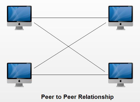
- In the peer to peer computer network model we simply use the same Workgroup for all the computers and a unique name for each computer in a computer network.
- There is no master or controller or central server in this computer network and computers join hands to share files, printers and Internet access.
- It is practical for workgroups of a dozen or less computers making it common environments, where each PC acts as an independent workstation and maintaining its own security that stores data on its own disk but which can share it with all other PCs on the network.
- Software for peer-to-peer network is included with most modern desktop operating systems such as Windows and Mac OS.
- Peer to peer relationship is suitable for small networks having less than 10 computers on a single LAN.
- In a peer to peer network each computer can not act as both a server and a client.
Advantages of Peer to Peer Networks
Peer to peer networks have following advantages:
1. Such networks are easy to set up and maintain as each computer manages itself.
2. It eliminates extra cost required in setting up the server.
3. Since each device is master of its own, they an: not dependent on other computers for their operations.
Disadvantages of Peer to Peer Networks
1. In peer-to-peer network, the absence of centralized server make it difficult to backup data as data is located on different workstations.
2. Security is weak as each system manages itself only.
3. There is no central point of data storage for file archiving.
Network Connection Types
There are different types of communications connection in existence between two endpoints., Home networks, and the Internet is the one of the most commonly used examples. Many type of devices are and several different methods are used connecting to these type of network architectures.
There are different advantages and disadvantages to this type of network architectures. Connecting computers to a these type of networks, we requires some networking framework to create the connections. The two different computer network connection types are getting discussed in this page are Point-to-Point Connection and multipoint connection. The main difference between them we can getting discussed with the help of below definition.
Point-to-Point Connection
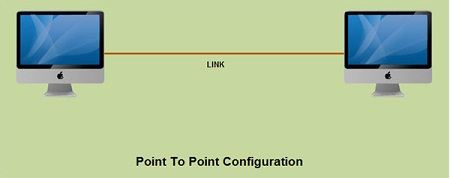
A point-to-point connection is a direct link between two devices such as a computer and a printer. It uses dedicated link between the devices. The entire capacity of the link is used for the transmission between those two devices. Most of today’s point-to-point connections are associated with modems and PSTN (Public Switched Telephone Network) communications. In point to point networks, there exist many connections between individual pairs of machines.
To move from sources to destination, a packet (short message) may follow different routes. In networking, the Point-to-Point Protocol (PPP) is a data link protocol commonly used in establishing a direct connection between two networking nodes. It can provide connection authentication, transmission encryption, and compression PPP is used over many types of physical networks including serial cable, phone line, trunk line, cellular telephone, specialized radio links, and fiber optic links such as SONET. PPP is also used over Internet access connections (now marketed as “broadband”).
Internet service providers (ISPs) have used PPP for customer dial-up access to the Internet, since IP packets cannot be transmitted over a modem line on their own, without some data link protocol. Two encapsulated forms of PPP, Point-to-Point Protocol over Ethernet (PPPoE) and Point-to-Point Protocol over ATM (PPPoA), are used most commonly by Internet Service Providers (ISPs) to establish a Digital Subscriber Line (DSL) Internet service connection with customers.
PPP is commonly used as a data link layer protocol for connection over synchronous and asynchronous circuits, where it has largely superseded the older Serial Line Internet Protocol (SLIP) and telephone company mandated standards (such as Link Access Protocol, Balanced (LAPB) in the X.25 protocol suite). PPP was designed to work with numerous network layer protocols, including Internet Protocol (IP), TRILL, Novell’s Internetwork Packet Exchange (IPX), NBF and AppleTalk.
Multipoint Connection
A multipoint connection is a link between three or more devices. It is also known as Multi-drop configuration. The networks havjng multipoint configuration are called Broadcast Networks. In broadcast network, a message or a packet sent by any machine is received by all other machines in a network. The packet contains address field that specifies the receiver. Upon receiving a packet, every machine checks the address field of the packet. If the transmitted packet is for that particular machine, it processes it; otherwise it just ignores the packet.
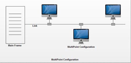
Broadcast network provides the provision for broadcasting & multicasting. Broadcasting is the process in which a single packet is received and processed by all the machines in the network. It is made possible by using a special code in the address field of the packet. When a packet is sent to a subset of the machines i.e. only to few machines in the network it is known as multicasting. Historically, multipoint connections were used to attach central CPs to distributed dumb terminals. In today’s LAN environments, multipoint connections link many network devices in various configurations.
What is a computer network? Advantages of Network .
A computer network consists of two or more computers that are linked in order to share resources such as printers and CD-ROMs, exchange files, or allow electronic communications. The computers on a computer network may be linked through cables, telephone lines, radio waves, satellites, or infrared light beams. [Read more…] about What is a computer network? Advantages of Network .
what is network? Types of Network
Computer Networks fall into three classes regarding the size, distance and the structure namely: LAN (Local Area Network), MAN (Metropolitan Area Network), WAN (Wide Area Network). Before we discussing about type of network we can discuss about what is a network. [Read more…] about what is network? Types of Network
What is Internetworking
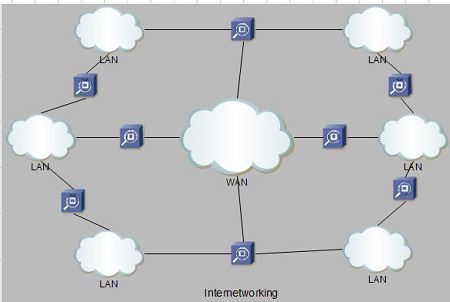
Internetworking started as a way to connect disparate types of computer networking technology. Computer network term is used to describe two or more computers that are linked to each other. When two or more computer LANs or WANs or computer network segments are connected using devices such as a router and configure by logical addressing scheme with a protocol such as IP, then it is called as computer internetworking.
Internetworking is a term used by Cisco. Any interconnection among or between public, private, commercial, industrial, or governmental computer networks may also be defined as an internetwork or “Internetworking“.
In modern practice, the interconnected computer networks or Internetworking use the Internet Protocol. Two architectural models are commonly used to describe the protocols and methods used in internetworking. The standard reference model for internetworking is Open Systems Interconnection (OSI).
Type of Internetworking
Internetworking is implemented in Layer 3 (Network Layer) of this model The most notable example of internetworking is the Internet (capitalized). There are three variants of internetwork or Internetworking, depending on who administers and who participates in them :
• Extranet
• Intranet
• Internet
Intranets and extranets may or may not have connections to the Internet. If connected to the Internet, the intranet or extranet is normally protected from being accessed from the Internet without proper authorization. The Internet is not considered to be a part of the intranet or extranet, although it may serve as a portal for access to portions of an extranet.
Extranet
An extranet is a network of internetwork or Internetworking that is limited in scope to a single organisation or entity but which also has limited connections to the networks of one or more other usually, but not necessarily, trusted organizations or entities .Technically, an extranet may also be categorized as a MAN, WAN, or other type of network, although, by definition, an extranet cannot consist of a single LAN; it must have at least one connection with an external network.
Intranet
An intranet is a set of interconnected networks or Internetworking, using the Internet Protocol and uses IP-based tools such as web browsers and ftp tools, that is under the control of a single administrative entity. That administrative entity closes the intranet to the rest of the world, and allows only specific users. Most commonly, an intranet is the internal network of a company or other enterprise. A large intranet will typically have its own web server to provide users with browseable information.
Internet
A specific Internetworking, consisting of a worldwide interconnection of governmental, academic, public, and private networks based upon the Advanced Research Projects Agency Network (ARPANET) developed by ARPA of the U.S. Department of Defense also home to the World Wide Web (WWW) and referred to as the ‘Internet‘ with a capital ‘I’ to distinguish it from other generic internetworks. Participants in the Internet, or their service providers, use IP Addresses obtained from address registries that control assignments.
Client Server Networks
• A Computer networking model where one or more powerful computers (servers) provide the different computer network services and all other user’of computer network (clients) access those services to perform user’s tasks is known as client/server computer networking model.
• In such networks, there exists a central controller called server. A server is a specialized computer that controls the network resources and provides services to other computers in the network.
• All other computers in the network are called clients. A client computer receives the requested services from a server.
• A server performs all the major operations like security and network management.
• All the clients communicate with each other via centralized server
• If client 1 wants to send data to client 2, it first sends request to server to seek permission for it. The server then sends a signal to client 1 allowing it to initiate the communication.
• A server is also responsible for managing all the network resources such as files, directories, applications & shared devices like printer etc.
• If any of the clients wants to access these services, it first seeks permission from the server by sending a request.
• Most Local Area Networks are based on client server relationship.
Client-server networking became popular in the late 1980s and early 1990s as many applications were migrated from centralized minicomputers and mainframes to computer networks of persona computers.
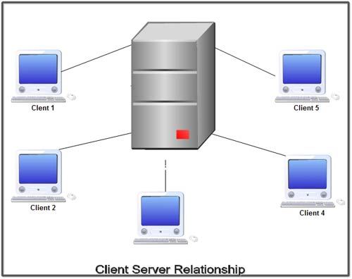
The design of applications for a distributed computing environment required that they effetely be divided into two parts: client (front end) and server (back end). The network model on which they were implemented mirrored this client-server model with a user’s PC (the client) typically acting as the requesting machine and a more powerful server machine to which it was connected via either a LAN or a WAN acting as the supplying machine. It requires special networking operating system. It provides user level security and it is more expensive.
Advantages of Client Server Networks
1. Centralized back up is possible.
2. Use of dedicated server improves the performance of whole system.
3. Security is better in these networks as all the shared resources are centrally administered.
4. Use of dedicated servers also increases the speed of sharing resources.
Disadvantages of Client Server Networks
1. It requires specialized servers with large memory and secondary storage. This leads to increase in the cost.
2. The cost of network operating system that manages the various clients is also high.
3. It requires dedicated network administrator.
Types of Servers
There are many type of Serves in the Computer Networking World. Server is a machine, that can be design for interconnecting the machines with each other.Many type of the functions are performed by the servers to facilitate different uses. Let us discussed first, what is a server before getting discuss about type of servers.
What is a Server
The word ‘server’ refers to a powerful specialized machine on which the server hardware, software, or a combination provides various services to other computers. A server can provide various functionalities, and they come in different types and sizes to facilitate different work or uses. When a Server and its clients computers are work together then we call it a client/server network, which provides us a centralized access to information, content, and stored data, etc. Now we can discussed the basic type of server in computer networking.
File servers
With a file server, the Computer Network client passes requests for computer network files or file records over a computer network to the file server. This form of computer network data service requires large bandwidth and can slow a computer network with many users down considerably. Traditional LAN (Local area Network) computing allows users to share resources, such as data files and peripheral devices, by moving them from standalone PCUs onto a Networked File Server (NFS).
Database servers
In database servers, clients passes SQL (Structured Query Language) requests as messages to the server and the results of the query are returned over the network. The code that processes the SQL request and the data resides on the server allowing it to use its own processing power to find the requested data, rather than pass all the records back to a client and let it find its owndata as was the case for the file server.
Transaction servers
Clients invoke remote procedures that reside on servers which also contains an SQL database engine. There are procedural statements on the server to execute a group of SQL statements (transactions) which either all succeed or fail as a unit. The applications based on transaction servers are called On-line Transaction Processing (OLTP) and tend to be mission-critical applications which require 1-3 second response time, 100% of the time and require tight controls over the security and integrity of the database.
The communication overhead in this approach is kept to a minimum as the exchange typically consists of a single request/reply (as opposed to multiple SQL statements in database servers). Application servers are not necessarily database centered but are used to server user needs, such as. download capabilities from Dow Jones or regulating a electronic mail process. Basing resources on a server allows users to share data, while security and management services, which are also based in the server, ensure data integrity and security.
Types of Computer Networks
Types of Computer Networks can be classified on various properties. The Computer networks can also be classified on the basis of Computer network technology used by them. There are two types of Computer networks in this category.
1. Broadcast Networks. In broadcast networks, a single communication channel is shared among all the computers of the network. This means, all the data transportation occurs through this shared channel. The data is transmitted in the form of packets. The packets transmitted by one computer are received by all others in the network. The destination of packet is specified by coding the address of destination computer in the address field of packet header.
On receiving a packet, every computer checks whether it is intended for it or not. If the packet is intended for it, it is processed otherwise, it is discarded. There is another form of broadcast networks in which the packets transmitted by a computer are received by a particular group of computers. This is called as “Multicasting”.
2. Point to Point or Store and Forward Networks. This is the other type of networks on the basis of transmission technology. The store and forward networks consist of several interconnected computers and networking devices. The data is transmitted in the form of packets. Each packet has its own source and destination address.
To go from a source to a destination, a packet on this type of network may first have to visit one or more intermediate devices or computers that are generally called as “routers”. The packets are stored on an intermediate router unless the output line is free. When the output line is free, it is forwarded to the next router. The routing algorithms are used to find a path from the source to destination. The routing algorithms play a very important role in this type of network.
What is a Computer Network? Uses of Computer Networks.
During 20th century the most important technology has been the information gathering, its processing and distribution. The computers and communications have been merged together and their merger has had a profound effect on the manner in which computer systems are organized. [Read more…] about What is a Computer Network? Uses of Computer Networks.